Pressure-type flow control device and method for preventing overshooting at start of flow control performed by said device

a flow control device and pressure-type technology, applied in the direction of engine diaphragms, diaphragm valves, instruments, etc., can solve the problem of overshooting of the controlled flow value, achieve the effect of preventing overshooting at the start of flow control, enhancing control responsiveness to flow changes, and significantly shortening the step-up time and step-down time in flow control

Active Publication Date: 2016-11-10
FUJIKIN INC
View PDF2 Cites 14 Cited by
  • Summary
  • Abstract
  • Description
  • Claims
  • Application Information

AI Technical Summary

Benefits of technology

[0037]In the present invention, the pressure-type flow control device includes: a main body provided with a fluid channel communicating between a fluid inlet and a fluid outlet and an exhaust channel communicating between the fluid channel and an exhaust outlet; a pressure control valve fixed to the fluid inlet side of the main body for opening or closing the upstream side of the fluid channel; a first pressure sensor for detecting the internal pressure of the fluid channel on the downstream side of the pressure control valve; an orifice provided in the fluid channel on the downstream side of the point of branching of the exhaust channel; an on / off valve for opening or closing the fluid channel on the downstream side of the first pressure sensor; and an exhaust valve for opening or closing the exhaust channel. Before the start of fluid flow control by the pressure-type flow control device, the pressure control valve and the exhaust valve are operated to forcibly exhaust gas in the fluid channel space between the pressure control valve and the on / off valve, whereby overshoot at the start of flow control can be prevented.
[0038]As a result, in the pressure-type flow control device according to the present invention, the control responsiveness to changes in the flow is enhanced, whereby the step-up time and step-down time in flow control can be significantly shortened, and also the time regulation is facilitated, making it possible to improve the so-called gas replaceability of the pressure-type flow control device, leading to improvement in the capacity utilization, improvement in the quality of semiconductor products, and the like.
[0039]Further, when the on / off valve to be provided in a fluid supply channel is an orifice-built-in on / off valve, the pressure-type flow control device can be further downsized. At the same time, when the exhaust valve is closed, such a flow control device can also be applied as an ordinary pressure-type flow control device.
[0040]In addition, when the fluid flow is subjected to so-called pulse flow control using the on / off valve provided in the fluid channel, the compliance of control is significantly improved because the internal pressure of the fluid channel on the orifice upstream side is reduced.

Problems solved by technology

This results in a problem in that when the flow control is re-started, due to the increased internal pressure of the fluid channel, the controlled flow value “overshoots” at the time of step-up.

Method used


Image

  • Pressure-type flow control device and method for preventing overshooting at start of flow control performed by said device
  • Pressure-type flow control device and method for preventing overshooting at start of flow control performed by said device
  • Pressure-type flow control device and method for preventing overshooting at start of flow control performed by said device

Examples


Embodiment Construction

[0048]Hereinafter, embodiments of the present invention will be described based on the drawings.

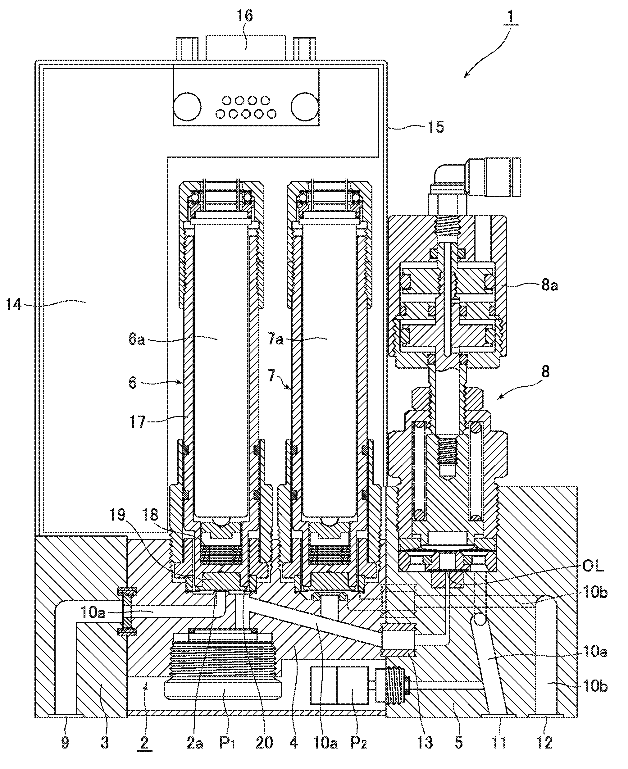
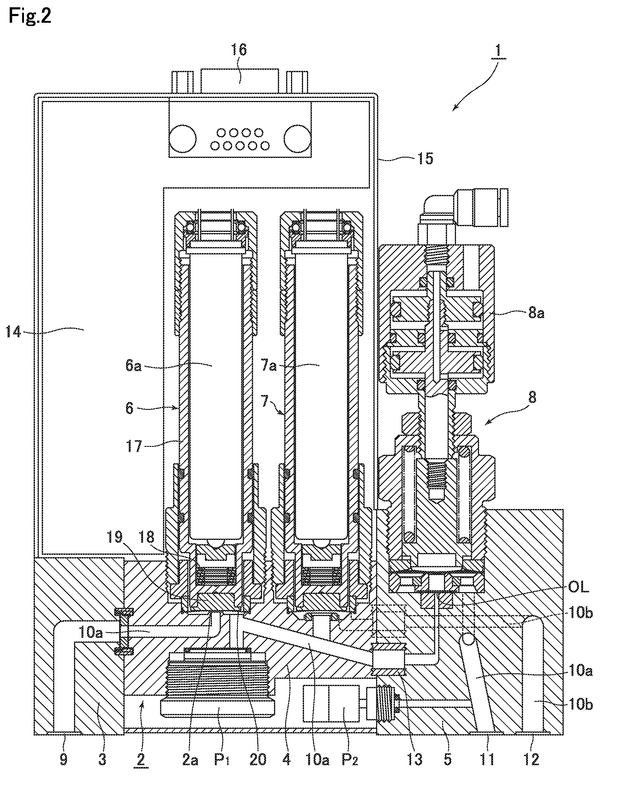
[0049]FIG. 1 is a system diagram showing the basic configuration of the pressure-type flow control device according to the present invention, FIG. 2 is longitudinal cross-sectional view showing the basic configuration of the pressure-type flow control device according to the present invention, and FIG. 3 shows a plan view (a) and a front view (b) of the pressure-type flow control device according to the present invention, as well as a partial enlarged cross-sectional view (c) of an orifice-built-in on / off valve.

[0050]In addition, FIG. 4 is a system diagram showing the configuration of a gas supply box using the pressure-type flow control device according to the present invention.

[0051]With reference to FIG. 1 to FIG. 3, the pressure-type flow control device 1 according to the present invention comprises a main body 2, a pressure control valve 6, an exhaust valve 7, a pneumatically actuate...


PUM


Abstract

The pressure-type flow control device includes: a main body provided with a fluid channel communicating between a fluid inlet and a fluid outlet and an exhaust channel communicating between the fluid channel and an exhaust outlet; a pressure control valve fixed to a fluid inlet side of the main body for opening or closing the upstream side of the fluid channel; a first pressure sensor for detecting the internal pressure of the fluid channel on the downstream side of the control valve; an orifice provided in the fluid channel on the downstream side of the point of branching of the exhaust channel; an on/off valve for opening or closing the fluid channel on the downstream side of the first pressure sensor; and an exhaust valve for opening or closing the exhaust channel.

Description

TECHNICAL FIELD[0001]The present invention relates to the improvement of a pressure-type flow control device. The present invention relates to a pressure-type flow control device having improved compliance of flow control and enhanced responsiveness at the time of flow step-up or flow step-down, thereby allowing for significant enhancement of the operation performance of a source gas supply device for a semiconductor manufacturing device, etc., and also to a method for preventing overshooting at the start of flow control thereby.BACKGROUND ART[0002]Conventionally, in source gas supply devices for semiconductor manufacturing devices, etc., heat-type flow control devices and pressure-type flow control devices have been widely used for controlling the supplied gas flow. In particular, the latter pressure-type flow control device FCS is, as shown in FIG. 5, composed of a control valve CV, a temperature detector T, a pressure detector P, an orifice OL, a computation control unit CD, and ...

Claims


Application Information

Patent Timeline
Patent Type & Authority Applications(United States)
IPC IPC(8): G05D7/06H01L21/67F16K31/12F16K7/14F16K31/02F16K31/06
CPCG05D7/0635F16K31/02H01L21/67253F16K31/12F16K7/14F16K31/06G05D7/0641F16K7/16F16K31/004
Inventor HIRATA, KAORUIKEDA, NOBUKAZUNISHINO, KOUJIDOHI, RYOUSUKESUGITA, KATSUYUKINAGASE, MASAAKI
Owner FUJIKIN INC
Why Eureka
Try Eureka