Multi-band antenna

a multi-band antenna and antenna technology, applied in the field of antennas, can solve the problems of increasing the manufacture cost of multi-band antennas, and the limit of the space of multi-band antennas, so as to reduce the coupling effect and parasitic radiation between sub-antennas, extend the effective distance, and extend the connection

Active Publication Date: 2016-11-10
RFS TECH INC
View PDF3 Cites 8 Cited by
  • Summary
  • Abstract
  • Description
  • Claims
  • Application Information

AI Technical Summary

Benefits of technology

[0016]By extending the effective distance proportionally to the frequency of a low-band sub-antenna for induction current, induced by the low-band sub-antenna in the high-band sub-antenna, to flow from the high-band sub-antenna dipole to the reflector, the coupling effect and parasitic radiation between the sub-antennas are reduced. Extending the effective distance for the induction current means extending connection between the high-band sub-antenna and the reflector, or having the same effect as such extension.

Problems solved by technology

However, that would greatly increase manufacture cost of multi-band antennas and space of the multi-band antennas would finally become a limit for further addition of such structures.

Method used


Image

  • Multi-band antenna
  • Multi-band antenna
  • Multi-band antenna

Examples


Embodiment Construction

[0033]Reference will now be made to embodiments of the invention, one or more examples of which are illustrated in the figures. The embodiments are provided by way of explanation of the invention, and are not meant as a limitation of the invention. For example, features illustrated or described as part of one embodiment may be used with another embodiment to yield still a further embodiment. It is intended that the invention encompass these and other modifications and variations as come within the scope and spirit of the invention.

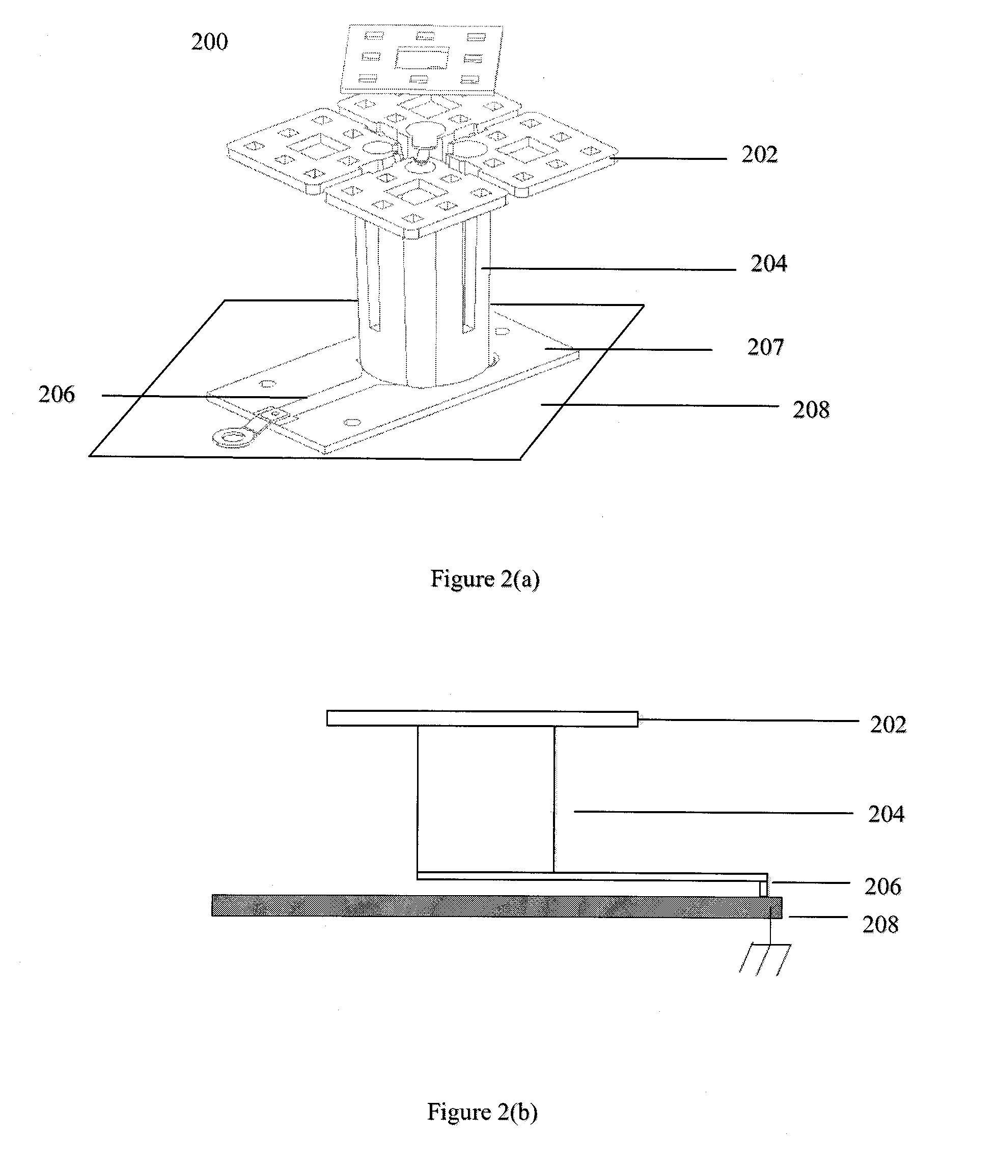
[0034]FIG. 2(a) is a 3-D illustration and FIG. 2(b) is schematic drawing of a high-band sub-antenna 200 of a multi-band in accordance with one embodiment of the present application. As illustrated in FIGS. 2(a) and (b), high-band sub-antenna 200 may include dipole arms 202, a support portion 204, and a reflector 208, wherein the support portion 204 is not connected to reflector 208 directly. Support portion 204 is separated from reflector 208 by a PCB boar...


PUM


Abstract

The present application provides a multi-band antenna, comprising at least one low-band sub-antenna; and at least one high-band sub-antenna comprising at least one high-band dipole and a reflector; wherein the high-band dipole and/or the reflector are/is structured and positioned so that current induced in the high-band sub-antenna by the low-band sub-antenna is directed to reflector over an extended effective distance in proportion to wavelength of the low-band sub-antenna.

Description

FIELD OF THE INVENTION[0001]The present invention relates to antennas, and in particular, relates to multi-band antennas.BACKGROUND OF THE INVENTION[0002]Antennas play an important role in communication systems and directly affect communication qualities. As wireless technology continues to thrive, multi-band antennas are used to implement higher speed and various types of services.[0003]A multi-band antenna usually includes an array of sub antennas that are generally categorized as low-band antennas and high-band antennas, which can cooperate at different frequency bands, as illustrated in FIG. 1(a).[0004]Due to the structure of multi-band antennas introduced above, coupling effect and parasitic radiation between the low-band antenna(s) and the high-band antenna(s) may greatly impair the performance of multi-band antennas and users' experience. FIG. 1(b) shows radiation pattern of a low-band sub-antenna array of a conventional multi-band antenna, which is abnormal due to the inter-...

Claims


Application Information

Patent Timeline
Patent Type & Authority Applications(United States)
IPC IPC(8): H01Q19/10H01Q5/385H01Q9/16
CPCH01Q19/10H01Q5/385H01Q9/16H01Q21/24H01Q1/246H01Q1/48H01Q1/521H01Q21/28H01Q21/26
Inventor CHAINON, SEBASTIENPLET, JEROMEHILARY, AURELIENCOQUILLE, GILLESWANG, JINJUJULIEN, THOMAS
Owner RFS TECH INC
Why Eureka
Try Eureka