A Fiber Mode Separator

A mode splitter and optical fiber technology, applied in cladding optical fiber, optical waveguide and light guide, etc., can solve the problems of difficult to achieve broadband matching, narrow working bandwidth, etc., and achieve effective separation, suppress interference, and increase the difference in coupling length

Active Publication Date: 2017-05-31
HUAWEI TEHCHNOLOGIES CO LTD
View PDF4 Cites 0 Cited by
  • Summary
  • Abstract
  • Description
  • Claims
  • Application Information

AI Technical Summary

Problems solved by technology

The dual-core fiber based on the coupling of single-mode fiber and few-mode fiber can also be used as a mode combiner. The disadvantage is that the fundamental mode of the single-mode fiber and the high-order mode of the few-mode fiber are coupled based on refractive index matching. Because it is difficult to achieve broadband matching, Its operating bandwidth is generally narrow, and coupling between different modes will occur [Few-mode optical fiber for mode-division multiplexing (few-mode optical fiber for mode-division multiplexing), Opt. Fiber Technol. ,2011, 17(5): 490-494】

Method used


Image

  • A Fiber Mode Separator
  • A Fiber Mode Separator
  • A Fiber Mode Separator

Examples


Embodiment 1

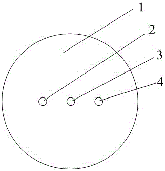
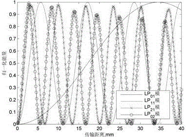
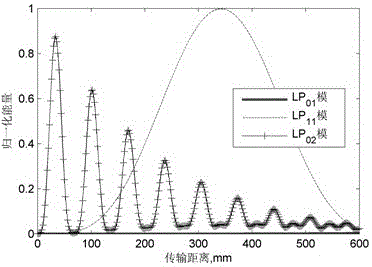
[0026] Preferred embodiments of the present invention are described below in conjunction with the accompanying drawings. Such as figure 1 As shown, this embodiment realizes LP 02 Die and LP 01 Die, LP 11 Separation between modules. The fiber matrix material 1 is pure silica, the radius of the three cores is 6.15 μm, and the refractive index difference between the core and the cladding is 0.012. The distance between the centers of adjacent cores is 22 μm. Light is input from the first core 2, LP 02 One mode is output from the third core 4 and the other modes are output from the first core 2 . Its coupling length curve is as image 3 shown. Visible, LP 02 The mode coupling length is much smaller than that of the other two modes. Take the fiber length as 33.5 mm. The energy of different modes output by the third core 4 is as follows: Figure 4 shown. Visible, in the wavelength range of 1.48-1.515μm, LP 02 The output power of the mode is greater than -1 dB, while th...


PUM


Abstract

The invention discloses an optical fiber mode separator. An optical fiber is composed of host materials and three fiber cores, wherein center lines of the fiber cores form a straight line, the center distances between the middle fiber core and the side fiber cores are the same, and refractive index distribution and fiber core dimensions of the fiber cores are the same. The optical fiber structure with the three fiber cores is adopted, therefore, coupling length difference among different modes is increased, the modes can be separated effectively, and clutter among different modes can be inhibited effectively. The optical fiber mode separator is used in a serial connection mode, and capable of effectively separating a plurality of different modes. Optical fiber parameters are identical completely, and therefore, difficult manufacturing and effect of parameter errors on coupling performance of optical fibers are avoided when the fiber cores different in dimensions are adopted.

Description

technical field [0001] The invention relates to the field of optical fiber communication, and is specifically divided into a mode separator for realizing separation between modes. Background technique [0002] In recent years, space division multiplexing has aroused widespread interest. The space division multiplexing system is realized by multi-core optical fiber or multi-mode optical fiber. Among them, when using multimode optical fiber, mode division multiplexing is realized through different modes (including different polarization modes). Since multiple different modes carry different information, mode division multiplexing can effectively improve the transmission capacity of the optical fiber. [0003] In the mode division multiplexing system, it is necessary not only to combine different modes into one optical fiber, but also to effectively separate different modes at the receiving end. That is, a mode combiner is required at the transmitting end and a mode separato...

Claims


Application Information

Patent Timeline
Patent Type & Authority Patents(China)
IPC IPC(8): G02B6/02G02B6/14
Inventor 陈明阳
Owner HUAWEI TEHCHNOLOGIES CO LTD
Why Eureka
Try Eureka