
Optical module

An optical module and laser technology, applied in the field of optical modules, can solve the problem that light source transmission cannot achieve efficient and stable coupling.

Pending Publication Date: 2020-11-17
HISENSE BROADBAND MULTIMEDIA TECH
View PDF14 Cites 2 Cited by
  • Summary
  • Abstract
  • Description
  • Claims
  • Application Information

AI Technical Summary

Problems solved by technology

Due to the reflection of light, the light source transmission between the laser box and the silicon photonic chip cannot achieve efficient and stable coupling

Method used

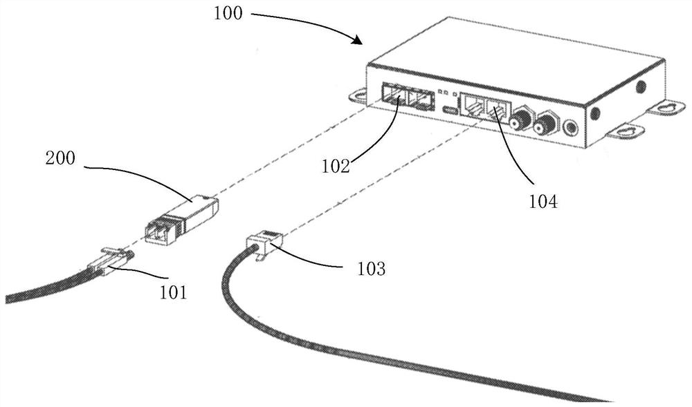
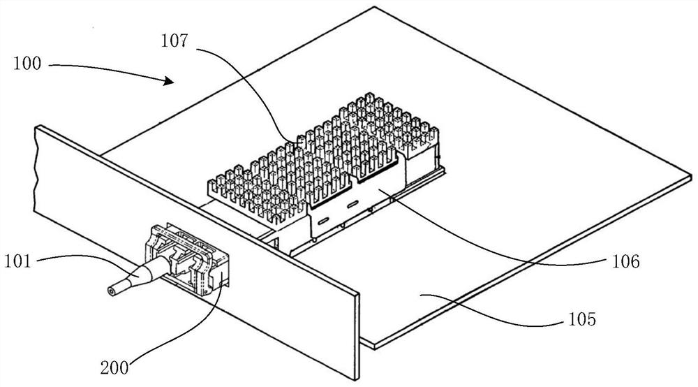
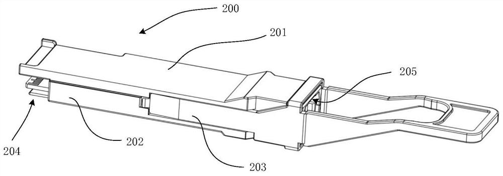

Image

  • Optical module
  • Optical module
  • Optical module

Examples


Embodiment Construction

[0023] Reference will now be made in detail to the exemplary embodiments, examples of which are illustrated in the accompanying drawings. When the following description refers to the accompanying drawings, the same numerals in different drawings refer to the same or similar elements unless otherwise indicated. The implementations described in the following exemplary examples do not represent all implementations consistent with this specification. Rather, they are merely examples of apparatuses and methods consistent with aspects of the present specification as recited in the appended claims.

[0024] The terms used in this specification are for the purpose of describing particular embodiments only, and are not intended to limit the specification. As used in this specification and the appended claims, the singular forms "a", "the", and "the" are intended to include the plural forms as well, unless the context clearly dictates otherwise. It should also be understood that the t...


PUM


Abstract

The invention provides an optical module. The optical module comprises a silicon optical chip and a laser box, the light emitting surface of the laser box emits light, and the optical coupling surfaceof the silicon optical chip receives the light from the laser box; the optical coupling surface of the silicon optical chip is arranged to be an inclined surface, and the axis direction of the laserbox and the optical coupling surface are arranged to be in a non-perpendicular relation. According to the optical module, the optical coupling surface in the silicon optical chip is set to be the inclined surface, and the axis direction of the laser box is set to be non-perpendicular to the optical coupling surface, so that an included angle is formed between incident light and reflected light formed on the optical coupling surface; therefore, the influence of the reflection of light on the optical coupling surface on the coupling between the laser box and the silicon optical chip is avoided.

Description

technical field [0001] The invention relates to the field of optical fiber communication, in particular to an optical module. Background technique [0002] Realizing the photoelectric conversion function by silicon photonics chips has become a mainstream solution currently adopted by high-speed optical modules. In the silicon photonics module, the silicon photonics chip is arranged on the surface of the circuit board, and is electrically connected to the circuit board by bonding. The silicon photonics chip receives external optical signals and transmits optical signals through an optical fiber array. Since the silicon material used in the silicon photonics chip is not an ideal light-emitting material for laser chips, and the light-emitting unit cannot be integrated in the silicon photonics chip manufacturing process, the silicon photonics chip also needs to provide light from an external light source such as a laser box. Due to the reflection of light, the light source tran...

Claims


Application Information

Patent Timeline
Patent Type & Authority Applications(China)
IPC IPC(8): G02B6/42
CPCG02B6/4296G02B6/4251G02B6/4204
Inventor 王华强孙祥勋郑龙杨思更
Owner HISENSE BROADBAND MULTIMEDIA TECH
Learn More