Zero export relay

a relay and zero-emission technology, applied in photovoltaics, power network operation systems integration, ac network voltage adjustment, etc., can solve the problems of reducing the attractiveness of system owners to export solar power to the grid, greenhouse gas emissions, and reducing the number of system owners, so as to prevent over-generation

Inactive Publication Date: 2016-11-10
GNG ELECTRICAL
View PDF3 Cites 6 Cited by
  • Summary
  • Abstract
  • Description
  • Claims
  • Application Information

AI Technical Summary

Benefits of technology

[0021]Preferably, the size of the first series and inverter may be determined by the requisite feed in tariff. When power is in a forward direction the controllable switch may connect said further series to compensate for the usage of load from the mains power supply. When forward power or load decreases the controllable switch may isolate said further series to prevent over generation from the renewable energy source.
[0022]Preferably, the system may further comprise any one or more of the following protection devices: (i) over voltage protection; (ii) under voltage protection; (iii) over frequency protection; (iv) under frequency protection; (v) differential frequency protection between the phases; (vi) phase failure protection; (vii) reverse power flow protection. (viii) rate of change of frequency (RoCoF); (ix) voltage vector shift (VVS); (x) output limitation; or (xi) re-active power control. Should any one of the protection devices be energised the system may isolate and protect the mains power supply.

Problems solved by technology

Traditional energy generation from coal results in greenhouse gas emissions that are rapidly being mandated for reduction.
With these changes it is evident that self-consumption of solar power will become the new norm, and exporting solar power to the grid will become less attractive for system owners.
On such a low rate, without affordable storage for the solar energy, exporting power to the grid is not the most efficient way to use it.

Method used


Image

  • Zero export relay
  • Zero export relay
  • Zero export relay

Examples


Embodiment Construction

[0034]The following description, given by way of example only, is described in order to provide a more precise understanding of the subject matter of a preferred embodiment or embodiments.

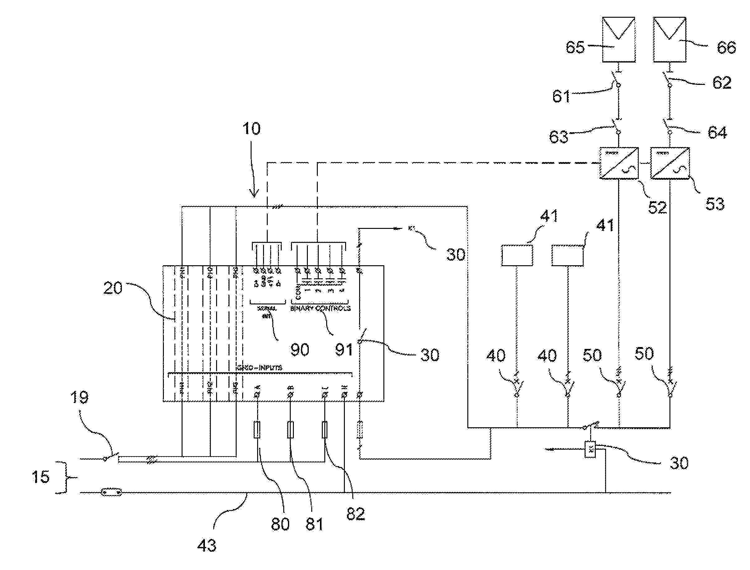
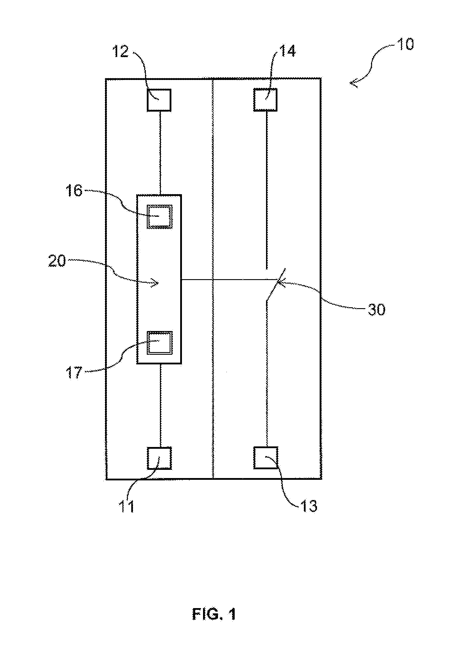
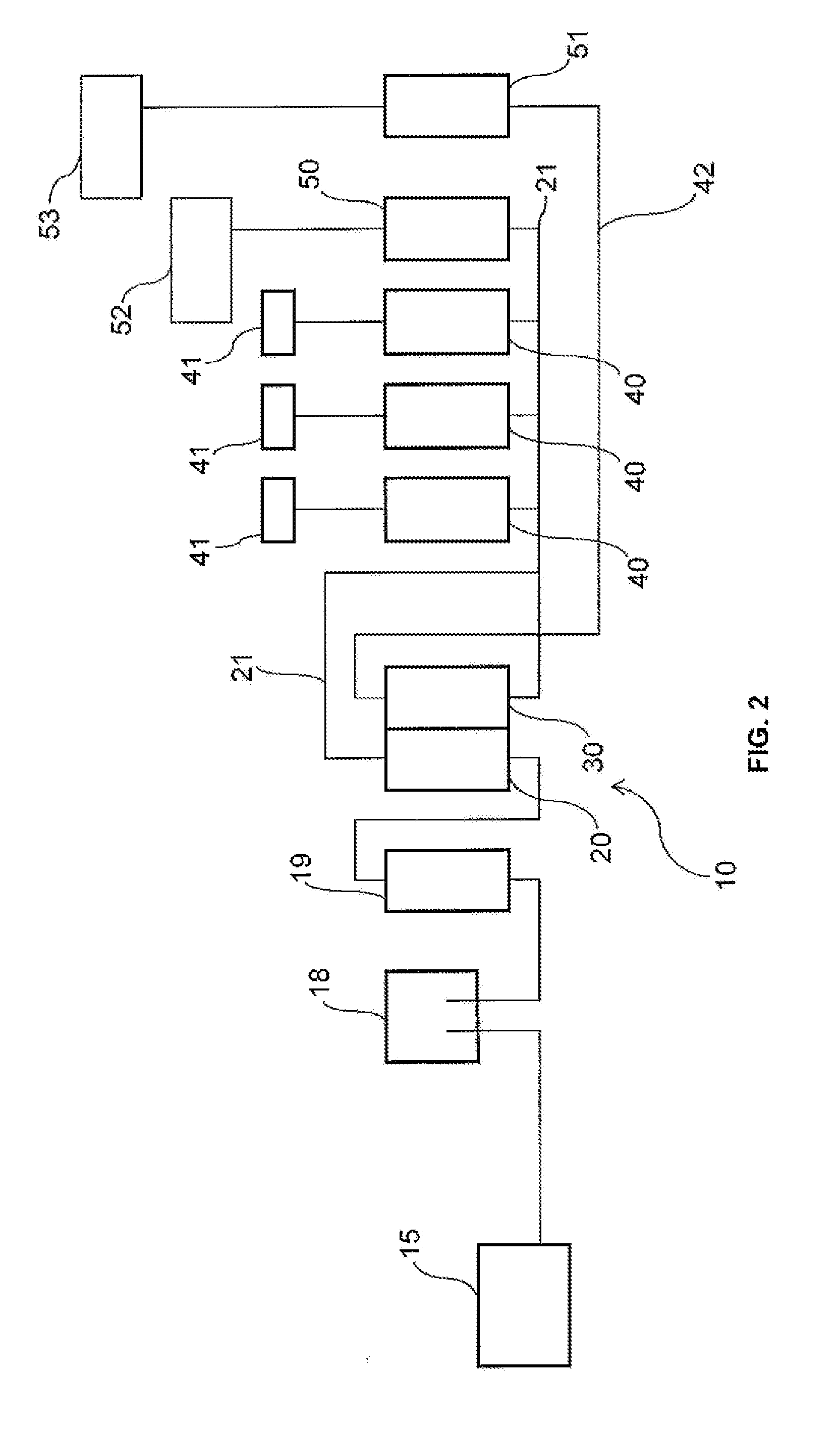
[0035]Described embodiments relate generally to a device for isolating and monitoring the power exported from a renewable energy source or system to a mains power supply and to systems for a renewable energy generation load compensation incorporating such a device. The device in accordance with the present invention is typically used for solar photovoltaic fed grid installations for the purpose of isolating the mains supply grid from the renewable energy source and the described embodiments are particularly suited to such purposes. Embodiments are not, however only limited to such use.

[0036]Photovoltaic (PV) is a method of generating electrical power by converting solar radiation into direct current electricity using semiconductors that exhibit the photovoltaic effect. Photovoltaic power generation...


PUM


Abstract

This invention relates in general to a device for isolating, controlling, limiting and supporting the power exported from the renewable energy source to the utility grid. The device comprising: a means for monitoring the direction of flow of power within the renewable energy source; a means for isolating the flow of power from the renewable energy source to the mains power supply, and wherein when a reverse power flow above agreed feed in or at least zero feed in or limited feed in is sensed by the means for monitoring between the renewable energy source to the mains power supply, the monitoring means signals the isolating means to open circuit the system and/or control/limit output of the system.

Description

FIELD OF THE INVENTION[0001]This invention relates in general to renewable energy generation within a utility grid. In particular, the present invention relates to a device for isolating, controlling and limiting the power exported from the renewable energy source to the utility grid. In the present invention the device has the ability to limit or have zero reverse power flow or feed in power from the renewable energy system to the utility grid.BACKGROUND OF THE INVENTION[0002]It should be noted that reference to the prior art herein is not to be taken as an acknowledgement that such prior art constitutes common general knowledge in the art.[0003]Electricity or power is an essential part of modern life. In residences, in businesses, in institutions and in other locations, consumers use electricity in a variety of ways. Utilities deliver power generated by power plants through a network of transmission and distribution lines. This network is hereinafter referred to as the “power tran...

Claims


Application Information

Patent Timeline
Patent Type & Authority Applications(United States)
IPC IPC(8): H02J3/46H02J3/16H02J13/00H02S50/00H02S40/32H02J3/38H02J3/14
CPCH02J3/46H02J3/382H02J3/16H02J13/00H02S50/00H02S40/32H02J3/14H02J11/00Y04S10/123H02J2300/10H02J2300/20H02J3/381Y02E10/50Y02E40/70Y04S20/222Y02B70/3225H02J3/388H02J2300/22H02J2300/28
Inventor ROGERS, GREGORY NEVILLE
Owner GNG ELECTRICAL
Why Eureka
Try Eureka