Enhanced nucleating beverage container, system and method

a beverage container and nucleation technology, applied in the direction of drinking vessels, transportation and packaging, packaging, etc., can solve the problems of different taste and/or loss of freshness, no longer fresh, undesired both from the consumer and vendor perspective, etc., to enhance nucleation, reduce surface tension, and increase both aesthetic appeal and aroma

Inactive Publication Date: 2016-11-17
TRULASKE JAMES A +1
View PDF3 Cites 5 Cited by
  • Summary
  • Abstract
  • Description
  • Claims
  • Application Information

AI Technical Summary

Benefits of technology

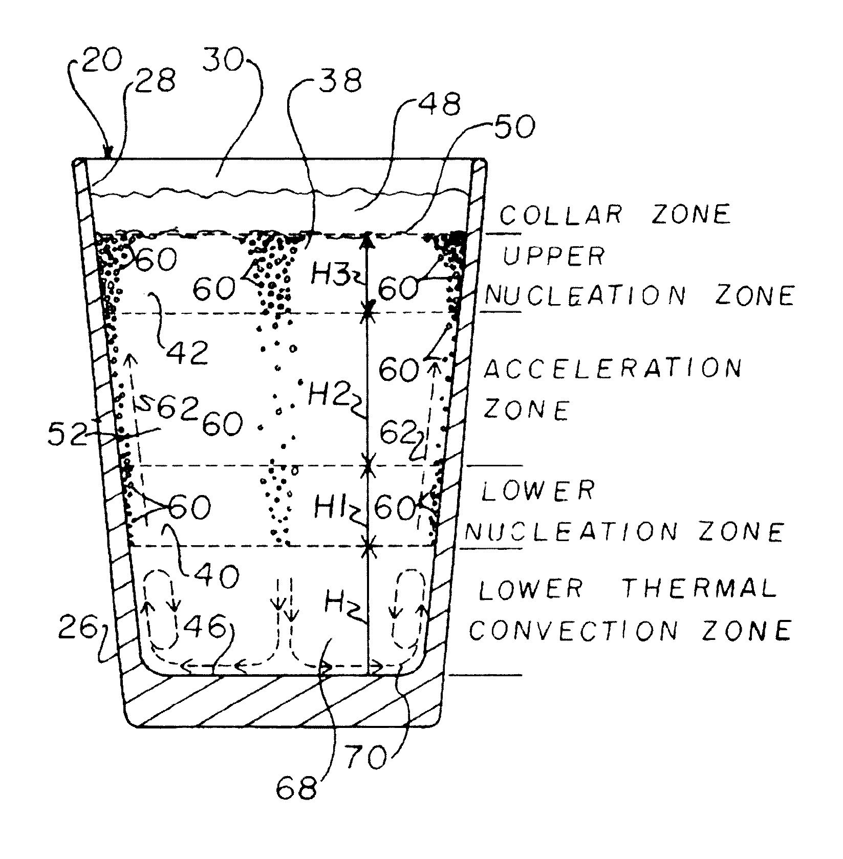
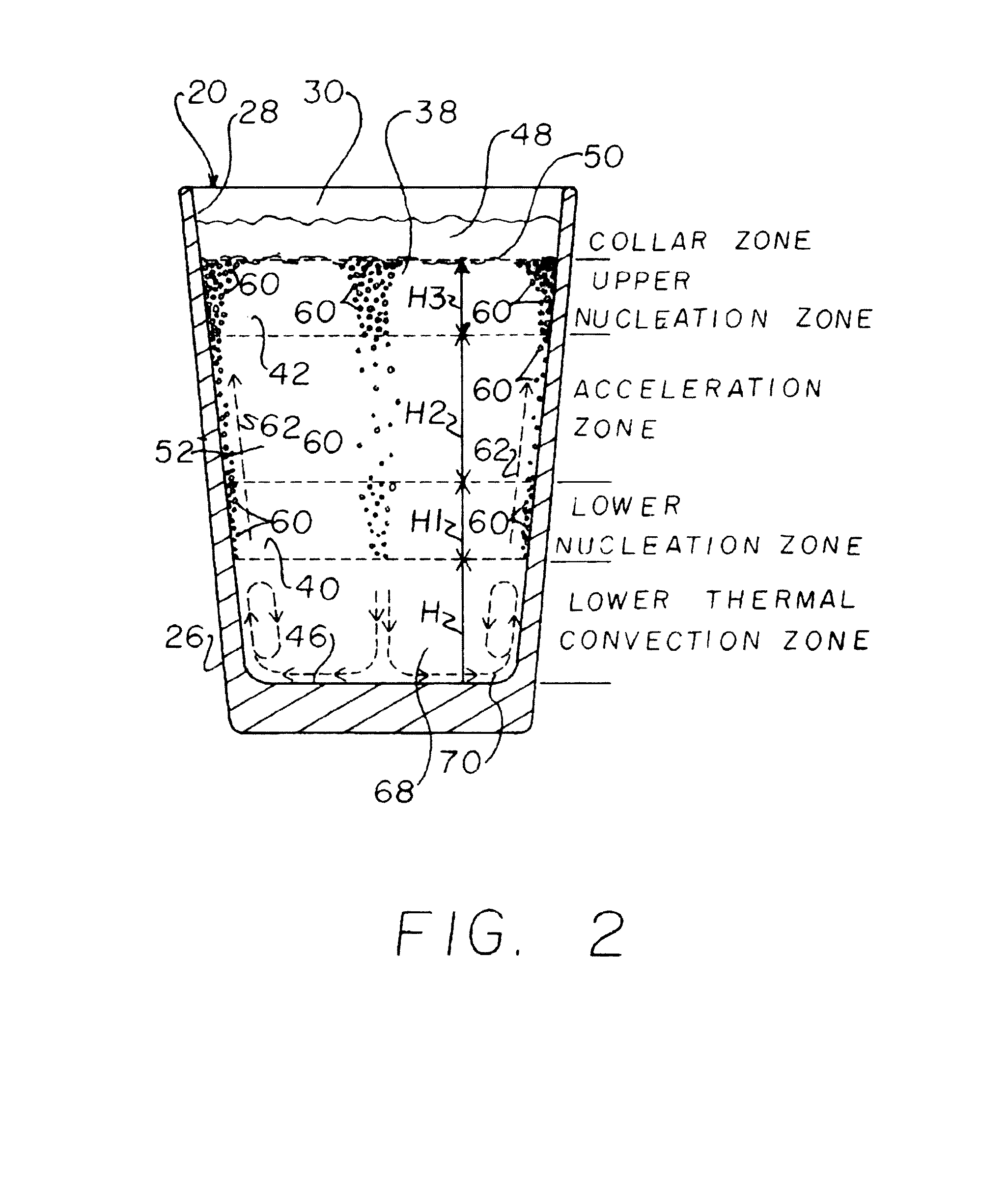
[0022]As an advantage of the invention, smaller, more numerous bubbles are generated, particularly at the upper nucleation sites, to provide the collar or head with a creamier foamed appearance. The smaller bubbles also have lower surface tension so they have been found to last longer than larger bubbles. This has been found to be advantageous for increasing both aesthetic appeal and aroma. One preferred manner of creating smaller, more numerous bubbles and the resulting finer foamed appearance according to the invention, is to locate multiple nucleation sites in zones at generally vertically aligned lower and higher elevations on the interior surface of the sidewall of the glass or container, in a manner and relationship such that bubbles that detach from the nucleation sites of the lower zone or zones enhance nucleation at higher sites, in particular, to create smaller and more numerous bubbles at those sites than would be generated with just multiple nucleation lines or sites acting independently. For applications wherein the sidewall of the container is tilted relative to vertical, such as a standard pint glass wherein the sidewall is at between about a 3 degree and a 15 degree angle to vertical, wherein the bubbles would ordinarily just rise generally vertically from the individual nucleation sites, the present invention configures the upper and lower sites in a cooperative manner so that the upper sites produce a greater number of smaller or finer bubbles.
[0023]One representative manner of enhancement according to the invention involves positioning the lower nucleation sites or zones in relation to upper sites, so that bubbles that detach from the lower sites or zones will pass closely by the upper sites or zone and cause or facilitate premature detachment of the bubbles attached at the upper sites, but without significant physical contact between the bubbles from the lower sites and those of the upper sites, so that increased bubble creation is achieved at the upper sites, but the bubbles don't coalesce into large bubbles to a significant extent.
[0024]According to a non-limiting preferred aspect of the invention for incorporating the invention into a common container, e.g., having sloped sidewalls, such as, but not limited to, various commercially available pint beer and ale glasses and the like, e.g., having a sidewall slope of between about 3-15 degrees from vertical (inclined to extending radially outwardly from the center of the cavity and upwardly) it is desired to cause the bubbles that detach from the lower nucleation sites or zones, to rise in a manner so as to stay close to the sidewall, and not just rise vertically as with known nucleation arrangements. To achieve this effect, it has been found that by providing the lower nucleation sites in a sufficient density such that the bubbles that detach and rise from a limited area in essentially a continuous flow or stream, a boundary layer flow can be developed, which will attach to the sidewall for a useful portion of the height of travel of the bubbles. Additionally, the lower nucleation sites can be spaced below the upper nucleation sites by an advantageous distance, so that the bubbles that rise from the lower sites will accelerate as they rise to achieve a velocity for better effecting premature detachment of the bubbles attached at the upper sites.
[0025]One preferred manner of creating the nucleation sites in a suitable configuration, e.g., size, density, durability, uses a laser to etch a two dimensional pattern of the nucleation sites at a high dpi (dots per inch) pulsating setting, such as but not limited to, between about 300 dpi and maximum dpi setting for the laser.
[0026]According to another preferred aspect of the invention, when the nucleation sites are provided in suitable density to form the desired boundary layer flow, and the lower nucleation zone or zones is / are positioned a suitable distance below the upper nucleation zone or zones, the concentrated rising bubble flow from the lower zone will flow closely past, but not significantly contact, the still attached bubbles at the higher nucleation sites, and cause a significant number of them to prematurely detach and rise also. Here, it should be noted that this spacial relationship between the lower and upper nucleation zones is desirably selected so as to avoid substantial collisions between and resultant coalescence of the respective bubbles into larger bubbles, which has been found to be possible as a result of characteristics of the boundary layer flow.
[0027]As a theory to explain the premature detachment of the bubbles within the upper zone, it is believed that the passing bubbles have an associated pressure wave, analogous to the bow wave created by movement of a boat through water, that is sufficient at the upward velocities achieved by the spacing of the lower zone from the upper zone, to exert forces against the attached bubbles, that in combination with buoyancy forces acting upwardly against the attached bubbles resulting from the gas contained therein, will be sufficient to cause the attached bubbles to detach, by overcoming the surface tension holding the bubbles to the surface of the sidewall. It is also believed that low pressure trailing regions following the rising bubbles, and / or the succession of multiple pressure waves, exert lateral forces against the attached bubbles, and may be a factor in the bubble creation and detachment, by drawing the existing attached bubbles toward the upward flow stream after passage of the rising bubbles and associated pressure waves, so that an oscillating pulsing action is exerted against the attached bubbles to facilitate detachment. The trailing lower pressure region when passing the nucleation sites and related trailing eddy currents are also believed to act as a catalyst to the nucleation, mainly to accelerate formation and growth of the attached bubbles prior to the premature detachment. As a result, it is observed that the bubbles detach prematurely and more frequently compared to when acted upon by buoyancy only in the absence of the flow of bubbles from below, so that the bubbles are generally smaller, which creates the creamier foamed head and its benefits.

Problems solved by technology

If the carbonation for a particular beer falls below its designated volume, it will typically be considered no longer fresh or even flat, and is undesired from both the consumer and vendor perspective.
Some hold the opinion that even a small deviation in the carbonation volume can be considered detrimental, as it will result in noticeably different taste and / or loss of freshness.
On the other hand, if the carbonation exceeds the designated volume, the beer may not dispense or pour as desired for that product, e.g., may be foamier with too large of a head, and may even be impossible to satisfactorily dispense in a liquid state.
The head can be created during the initial dispensing or pouring of the beer, but if too short or thin, may diminish unacceptably within less than 2 minutes or so, which lessens the presentation effect and appeal of the beer amongst many consumers.
Examples of typical unacceptable degradation of the head include substantial lack or disappearance of the foam, and breaking up of the foam, such that the upper surface of the beer is largely visible, so as to suggest lack of freshness or flatness, that is, loss of carbonation.
This is particularly undesirable when a mass market beer or ale is served beside a craft beer having a creamier head, as it makes the mass market beer appear less desirable.
One observed problem is that the bubbles can burst immediately upon reaching the surface, or reside for some time there and eventually burst, if the beverage is not consumed before that time.
Another observed problem is that rising bubbles can collide and coalesce into larger bubbles, which are less aesthetically desirable in the opinion of many.

Method used


Image

  • Enhanced nucleating beverage container, system and method
  • Enhanced nucleating beverage container, system and method
  • Enhanced nucleating beverage container, system and method

Examples


Embodiment Construction

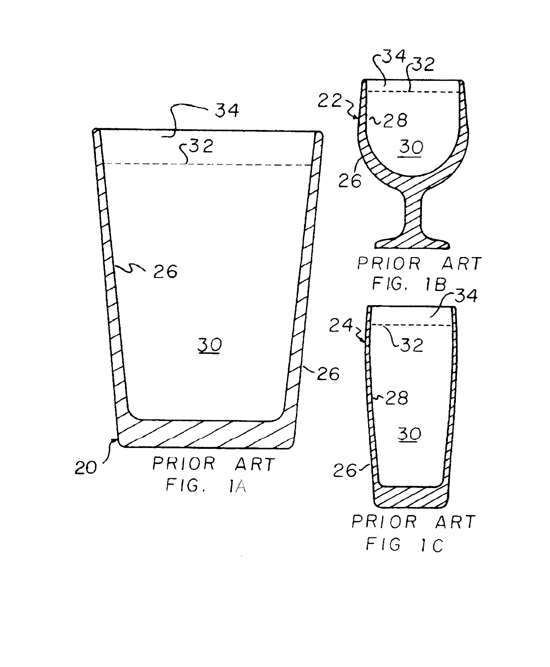
[0057]Referring now to the drawings, FIGS. 1A, 1B and 1C, show representative commercially available prior art beverage containers 20, 22, and 24, to illustrate just a few of the types of containers with which the present invention can be used. Container 20 is a conventional widely commercially available pint glass container, container 22 is a bowl style, and container 24 is a tulip style, each of which can be made of a suitable material, such as, but not limited to, glass or plastics, and each of which can be generally defined as including a sidewall 26 having a generally upstanding inner surface 28 bounding an upwardly open cavity 30 for receiving and holding a liquid beverage, which for purposes here will be a carbonated beverage, particularly a beer, ale, or stout. These and any of the other containers with which the invention is used can be round, oval other curved shape, or polygonal in sectional shape when viewed from above. Here, it should be understood that the present inve...


PUM

PropertyMeasurementUnit
heightaaaaaaaaaa
volumesaaaaaaaaaa
volumesaaaaaaaaaa

Abstract

A nucleating beverage container, system, and method, for effervescent beverages, incorporating nucleating features or sites at different elevations about a cavity of the container, configured to cooperate to generate an enhanced amount of smaller bubbles that will rise within and accumulate on the surface of the beverage as a collar or head, designable to do so without reducing the carbonation of the beverage so as to degrade taste or go flat within a prescribed time, and which can limit thermal convection of the beverage within a lower region of the container, to reduce warming and degradation of quality of the last to be consumed portion of the beverage.

Description

[0001]This application is submitted under 35 U.S.C. 371 claiming priority to PCT patent application Serial No. PCT / US2015 / 26727, filed Apr. 20, 2015, which application claims the benefit of U.S. Provisional Application No. 61 / 981,320, filed Apr. 18, 2014.TECHNICAL FIELD[0002]This invention relates generally to a nucleating beverage container, system, and method, particularly for carbonated and other effervescent beverages, incorporating nucleating features or sites at different elevations about a cavity of the container, configured to cooperate to generate an enhanced amount of smaller bubbles rising within and accumulating on the surface of the beverage, and which can be designed so as to do so without reducing the carbonation or other dissolved gas or gases of the beverage so as to degrade taste or go flat within a certain time, and which can limit thermal convection of the beverage within a lower region of the container, to reduce warming and degradation of quality of the last to...

Claims


Application Information

Patent Timeline
Patent Type & Authority Applications(United States)
IPC IPC(8): B01F3/04A47G19/22B65D85/73A23L2/54
CPCB01F3/04794B01F3/04439A23L2/54A23V2002/00B65D85/73B01F2003/049A47G19/2233B67D1/08C12H1/12B01F23/2361B01F23/2319B01F23/237621
Inventor TRULASKE, JAMES A.SCHMITT, STEPHEN M.
Owner TRULASKE JAMES A
Why Eureka
Try Eureka