Machining system for adjusting number of revolutions of machining tool and feed speed of workpiece

Active Publication Date: 2016-11-17
FANUC LTD
View PDF1 Cites 7 Cited by
  • Summary
  • Abstract
  • Description
  • Claims
  • Application Information

AI Technical Summary

Benefits of technology

[0007]The present invention provides a machining system which is

Problems solved by technology

When the workpiece is pressed against the machining tool of the processing machine by the robot, the machining tool may be deteriorated (e.g., wearing of the blade or abrasive) depending on the material of the workpiece or machining time, etc.
For example, it is necessary to per

Method used


Image

  • Machining system for adjusting number of revolutions of machining tool and feed speed of workpiece
  • Machining system for adjusting number of revolutions of machining tool and feed speed of workpiece
  • Machining system for adjusting number of revolutions of machining tool and feed speed of workpiece

Examples


first embodiment

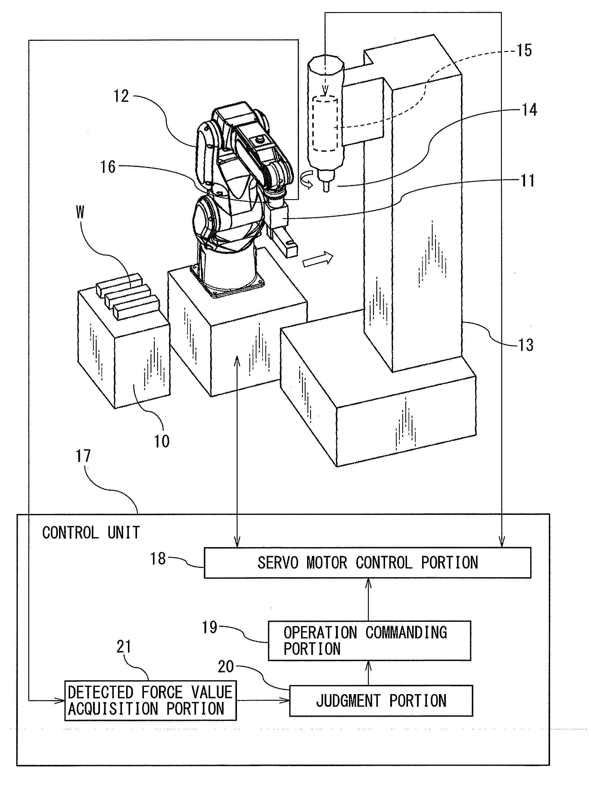
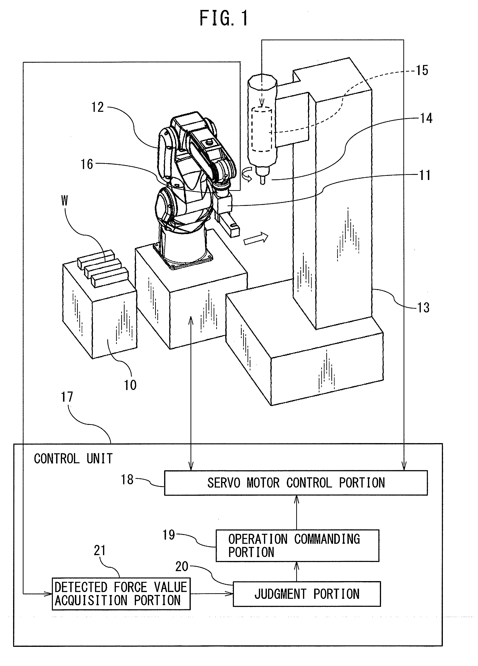
[0026]FIG. 1 shows a structure of the machining system according to the first embodiment.

[0027]The machining system according to the first embodiment comprises a workpiece stage 10 which places a workpiece W at a predetermined position, a robot 12 having a hand 11 attached to an arm tip thereof to grip the workpiece W, and a processing machine 13 installed in the range of movement of the hand 11 of the robot 12. The robot 12 is a multi-articulated vertical manipulator. The processing machine 13 has a machining tool 14 by which the workpiece W is machined, and a machining tool servo motor 15, which is incorporated in the spindle which rotates the machining tool 14.

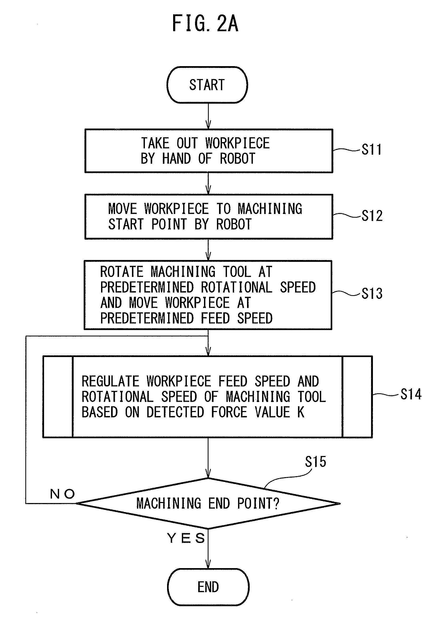
[0028]In the present invention, a cutter, grinder, or an end mill, etc., is used as the machining tool 14 to perform a machining process, such as burring, polishing or grinding on the workpiece W. After the workpiece W on the workpiece stage 10 is grasped by the hand 11 of the robot 12, the grasped workpiece W is moved to t...

second embodiment

[0053]Next, the second embodiment will be discussed below. The same components as those in the first embodiment are assigned the same reference numerals and no duplicate explanation thereof will be given hereinafter. Only the components different from those in the first embodiment will be described below.

[0054]FIG. 3 shows the structure of the machining system according to the second embodiment.

[0055]In the first embodiment illustrated in FIG. 1, the force sensor 16 is provided at the wrist portion between the arm tip of the robot 12 and the hand 11. However, the force sensor 16 may be provided on not the robot 12 but the processing machine 13.

[0056]Namely, in the second embodiment, the force sensor 16 is provided on the spindle of the processing machine 13 as shown in FIG. 3. More specifically, the force sensor 16 is arranged between the servo motor 15 for the machining tool and the machining head 22 which is rotated by the machining tool servo motor 15. The machining tool 14 is de...

third embodiment

[0059]The third embodiment will be discussed below. The same components as those in the first embodiment are assigned the same reference numerals and no duplicate explanation thereof will be given hereinafter. Only the components different from those in the first embodiment will be described below.

[0060]FIG. 4 shows the structure of the machining system according to the third embodiment.

[0061]In the third embodiment, the control unit 17 includes therein a frequency analyzing portion 23, as shown in FIG. 4.

[0062]More specifically, the frequency analyzing portion 23 performs a frequency analysis, e.g., FFT (Fast Fourier Transform) analysis of the history of the detected force value K of the force sensor 16 which is monitored by the detected force value acquisition portion 21. The frequency analyzing portion 23 resolves the records of the detected force value K of the force sensor 16 into a plurality of frequency components by the FFT analysis and extracts a specific frequency componen...


PUM


Abstract

A machining system of the present invention includes a robot having a hand, a processing machine to rotate a machining tool, a control unit which controls the processing machine and the robot so as to rotate the machining tool and press a workpiece held by the hand against the machining tool to thereby machine the workpiece, and a force sensor which detects force acting between the workpiece and the machining tool when the workpiece is pressed against the machining tool by the robot and is machined by the machining tool. The control unit regulates the workpiece feed speed of the robot and the rotational speed of the machining tool so that the force value detected by the force sensor is between a predetermined upper threshold and a predetermined lower threshold.

Description

BACKGROUND OF THE INVENTION[0001]1. Field of the Invention[0002]The present invention relates to a machining system provided with a robot which transfers a workpiece to a processing machine.[0003]2. Description of the Related Art[0004]Conventionally, a workpiece is transferred to a processing machine by a robot and is machined by a machining tool of the processing machine. In particular, in a machining operation, such as burring, polishing, or grinding, there are cases where the workpiece held by a hand of a robot is machined by a machining tool which is rotating while pressing the workpiece against the machining tool. In this connection, Japanese Patent Application Laid-Open No. 2008-142810 discloses a method for adjusting the movement of an arm portion of a robot so as to obtain an appropriate magnitude of force acting between the workpiece and the machining tool during the machining operation. Furthermore, the aforementioned Patent Application Laid-Open No. 2008-142810 discloses ...

Claims


Application Information

Patent Timeline
IPC IPC(8): B23Q15/013G05B19/402B23Q15/08B23Q7/04B23Q17/09
CPCB23Q15/013B23Q7/047B23Q17/0966B23Q15/08Y10S901/46G05B2219/50391G05B2219/49108Y10S901/02Y10S901/31G05B19/402B23Q5/28B25J9/1633B25J9/1653B25J9/1694B23Q17/0971G05B19/4166G05B2219/50326B25J11/005
Inventor FURUYA, YOSHITAKE
Owner FANUC LTD
Why Eureka
Try Eureka