
Hub And Spoke System For Detecting And Locating Gas Leaks

a spectroscopy system and hub-and-stalk technology, applied in the field of apparatus and methods for detecting and locating gas leaks, can solve the problems of large instrument distortion, low wavelength resolution of mobile ftir systems, and inability to detect, locate, and size methane leaks at kilometer scale standoff distances

Active Publication Date: 2016-11-17
THE UNITED STATES OF AMERICA AS REPRESENTED BY THE SECRETARY OF THE COMMERCE +1
View PDF2 Cites 10 Cited by
  • Summary
  • Abstract
  • Description
  • Claims
  • Application Information

AI Technical Summary

Benefits of technology

The patent describes a new device and method for detecting gas leaks using a laser and a dual comb spectrometer. The device is designed to be sensitive, accurate, and calibration-free, and can detect gas leaks over long distances with high accuracy. The method combines a line of sight sensor with a high resolution transport model and inversion model to locate gas leaks. The device and method could be used to detect and locate gas leaks in a cost-effective way.

Problems solved by technology

Mobile FTIR systems suffer from low wavelength resolution (large instrument distortion), and have thus far only demonstrated ˜5-10% measurement uncertainty for trace GHGs, which is far too great to detect, locate, and size methane leaks at kilometer scale standoff distances.
High precision, long-term stability, and accuracy is difficult due to turbulence-induced laser intensity fluctuations and interference from overlapping absorption of other molecules that are not included in spectral fits.
Sparse wavelength laser systems also do not typically measure other species, temperature, pressure, or water vapor.
These spectrometers enable very high sensitivity with short measurement times, but require periodic calibration, and are expensive.
Some focus on making flux measurements because they are not stable over long periods of time.
Others lack the measurement precision needed to identify smaller leaks or need to be calibrated often and corrected for effects of temperature, pressure, humidity, or other interfering species (possibly requiring regular access to the well pad).

Method used


Image

  • Hub And Spoke System For Detecting And Locating Gas Leaks
  • Hub And Spoke System For Detecting And Locating Gas Leaks
  • Hub And Spoke System For Detecting And Locating Gas Leaks

Examples


Embodiment Construction

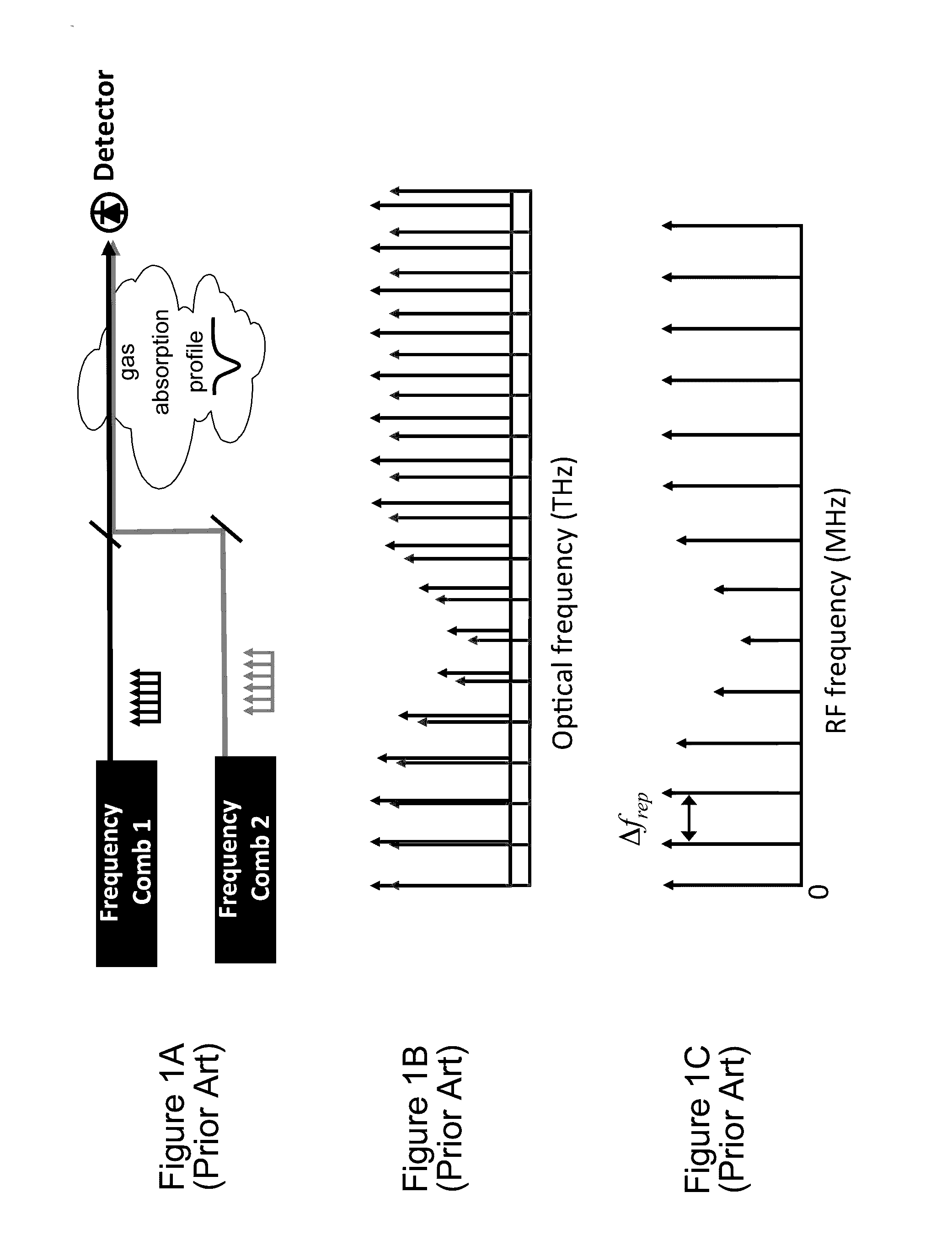
[0020]FIGS. 1A-1C (Prior Art) illustrate the operation of a dual comb spectroscopy (DCS) system that is useful in the gas detection portion of the present invention 1A (Prior Art) is a schematic block diagram illustrating the process of passing two frequency combs (e.g. near infrared light) having slightly different tooth spacings through a gas and detecting the resulting light. FIG. 1B shows the two frequency combs after the light passes through the gas, so that some light frequencies have been absorbed by the gas. FIG. 1C illustrates the resulting heterodyne interference signals at the detector, for example at rf frequencies.

[0021]DCS overcomes the key limitations of single or sparse wavelength absorption or LIDAR approaches: it enables accurate correction of the baseline laser intensity, and simultaneous measurement of CH4, 13CH4, H2O, other species (such as ethane and propane), temperature, and pressure. It therefore reports interference-free, true dry-air mole fractions that ac...


PUM


Abstract

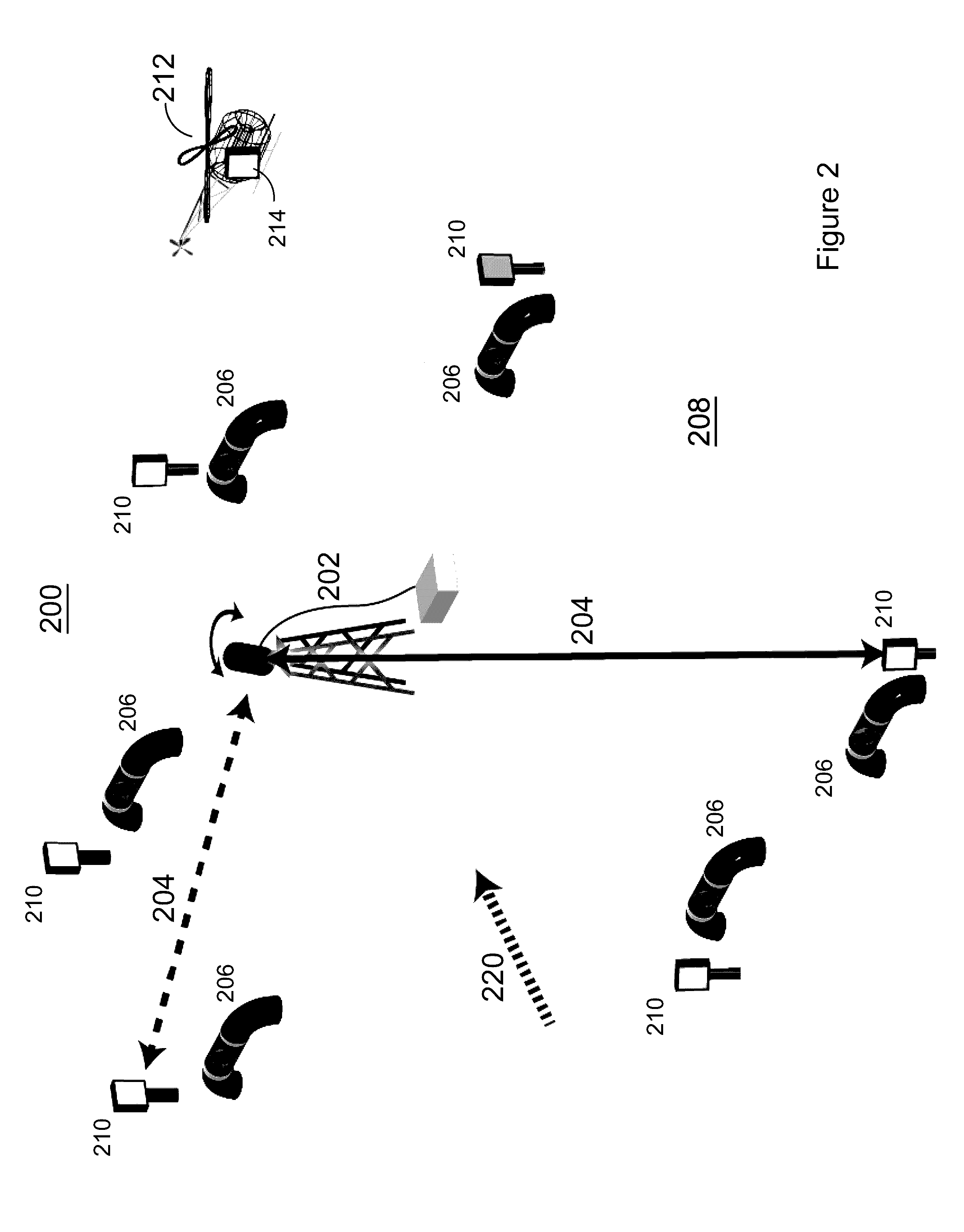
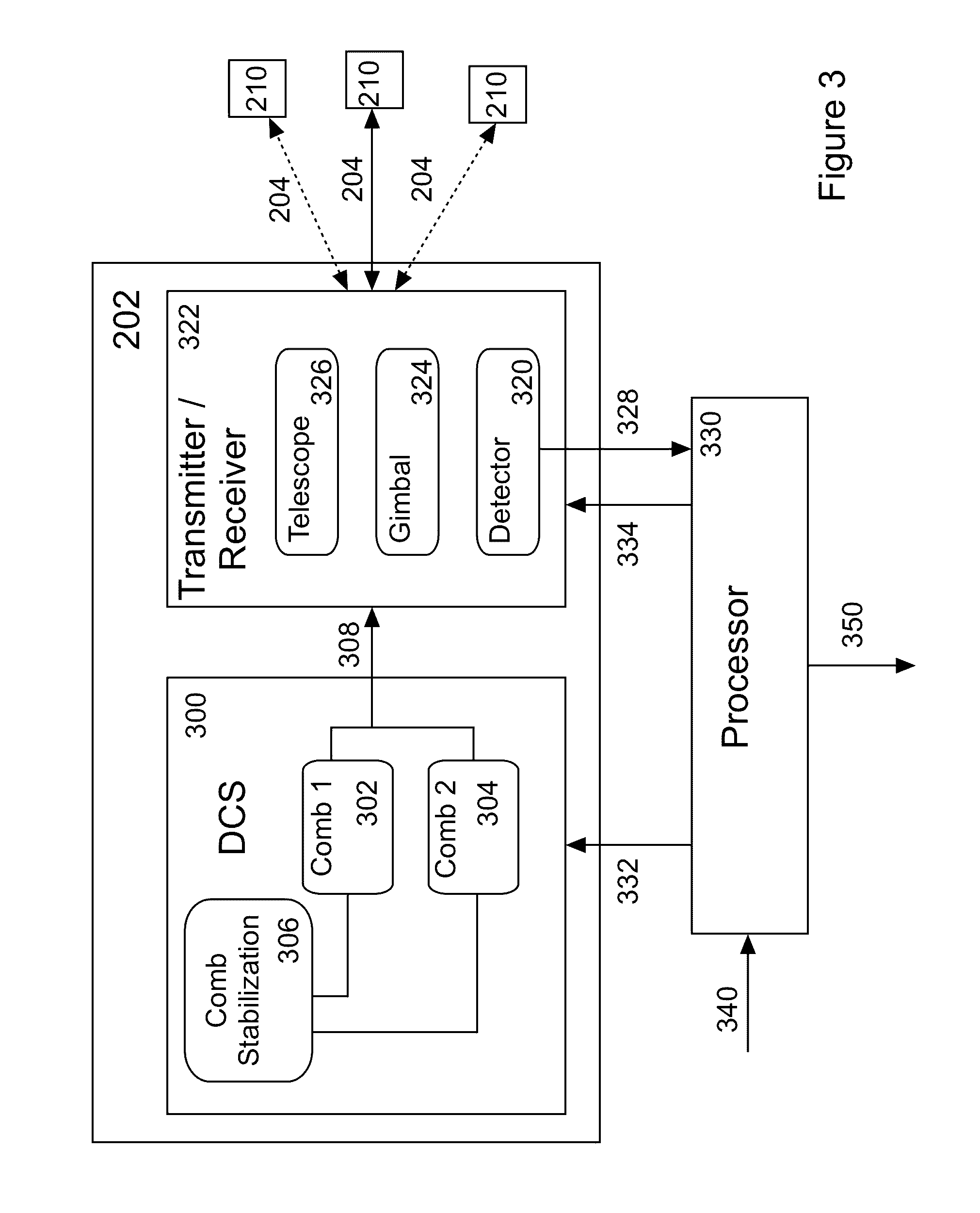
A system for detecting gas leaks and determining their location and size. A data gathering portion of the system utilizes a hub and spoke configuration to collect path-integrated spectroscopic data over multiple open paths around an area. A processing portion of the system applies a high resolution transport model together with meteorological data of the area to generate an influence function of possible leak locations on gas detector measurement paths, and applies an inversion model to the influence function and the spectroscopic data to generate gas source size and location.

Description

[0001]U.S. Pat. No. 8,564,785 is incorporated herein by reference. Provisional application for patent No. 62 / 160,163, filed 12 May 2015 is incorporated herein by reference.[0002]This invention was made with government support under grant number DE-AR0000539 awarded by the U.S. Department of Energy. The government has certain rights in the invention.BACKGROUND OF THE INVENTION[0003]1. Field of the Invention[0004]The present invention relates to apparatus and methods for detecting and locating gas leaks. In particular, the present invention relates to a hub and spoke spectroscopy system for detecting and locating methane leaks.[0005]2. Discussion of Related Art[0006]Current open-path techniques that are capable of measuring methane leaks over long paths include diode laser-based absorption systems, LIDAR systems, and FTIR-based systems. Mobile FTIR systems suffer from low wavelength resolution (large instrument distortion), and have thus far only demonstrated ˜5-10% measurement uncert...

Claims


Application Information

Patent Timeline
Patent Type & Authority Applications(United States)
IPC IPC(8): G01V8/10G01W1/00G01V99/00
CPCG01V8/10G01W1/00G01V99/005G01M3/202G01J3/42G01N21/3504G01J3/021G01N2021/3513G01N2201/1211G01N2201/1214
Inventor RIEKER, GREGORY BCODDINGTON, IANNEWBURY, NATHAN RPRASAD, KULDEEPKARION, ANNA
Owner THE UNITED STATES OF AMERICA AS REPRESENTED BY THE SECRETARY OF THE COMMERCE
Learn More