
Eureka
For R&D, Eureka makes reading and utilizing patents & technical documents easy.
Eureka AIR
Designed for self-driven R&D workflows. Generate viable solutions, solve complex R&D challenges, empower your innovation with AI.

Eureka Materials
Designed for material experts only. Revolutionize your material R&D, from search, analyze, to developing new materials.

TechResearch
Generate reliable direction feasibility study reports for your R&D in just a few steps.

TechSeek
Discover and master advanced knowledge NOW. Basics, ideas, possibilities, all at once.

TechMind
As an expert in R&D Theories, TechMind can generates customized viable solutions instantly.

TechRisk
Analyze your overall solution with one click, know your potential R&D risks in advance.

TechMonitor
Get weekly tech updates, stay abreast of the latest tech innovations and key insights.
Electric power conversion device
a power conversion device and three-phase technology, applied in power conversion systems, ac network circuit arrangements, electrical equipment, etc., can solve the problems of complex transformer configuration and increase in transformer cost, and achieve the effect of reducing the rated current of the power conversion uni
- Summary
- Abstract
- Description
- Claims
- Application Information
AI Technical Summary
Benefits of technology
Problems solved by technology
Method used
Image

Examples
embodiment 1
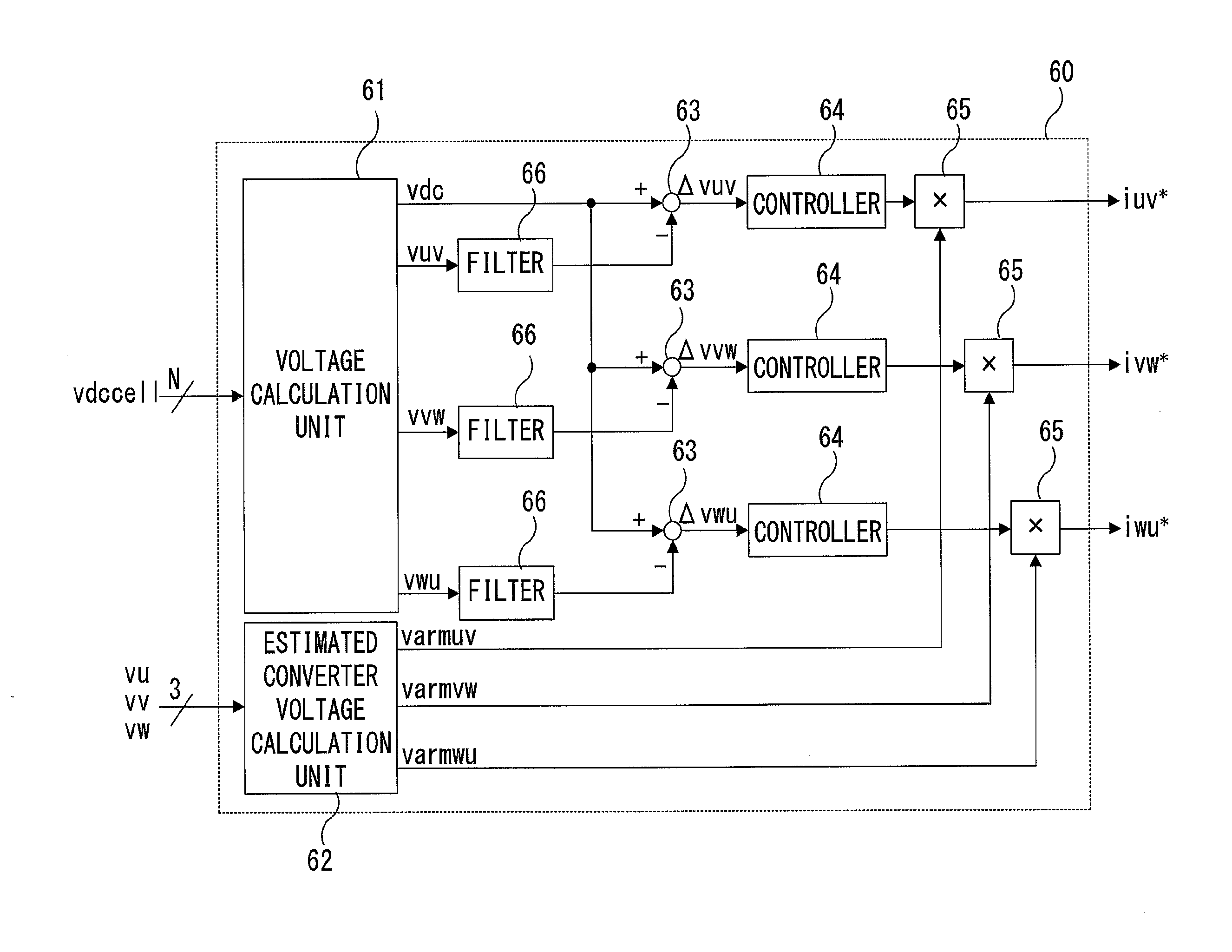
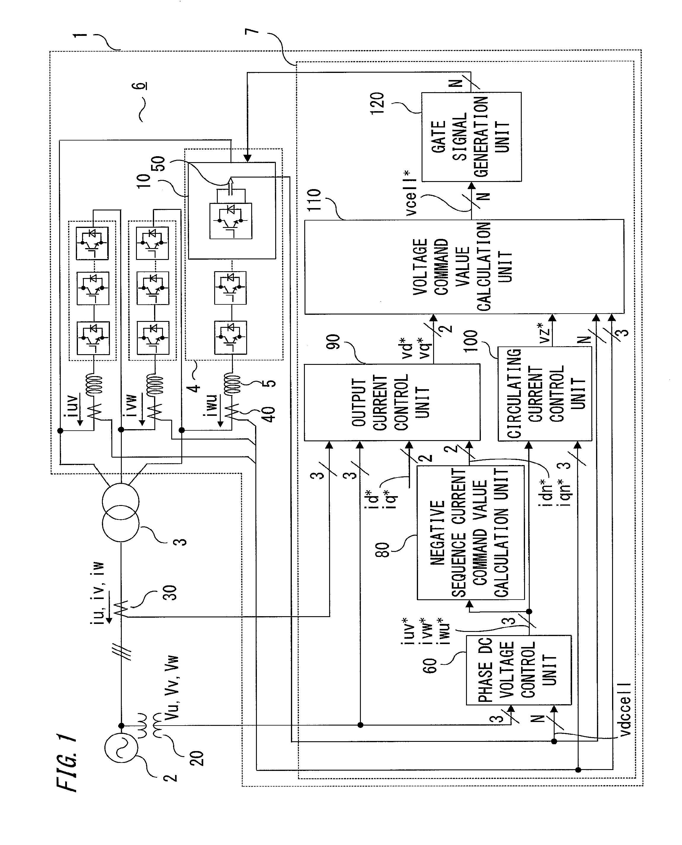
[0030]Embodiment 1 relates to an electric power conversion device including a power conversion unit and a converter control unit, wherein the converter control unit includes three voltage control systems (phase DC voltage control unit, overall voltage control unit, cell DC voltage control unit), two current control systems (output current control unit, circulating current control unit), two calculation units (negative sequence current command value calculation unit, phase voltage command value calculation unit), and a gate signal generation unit, and imbalance of cell DC voltages among phases due to grid imbalance is controlled by circulating current and negative sequence current.
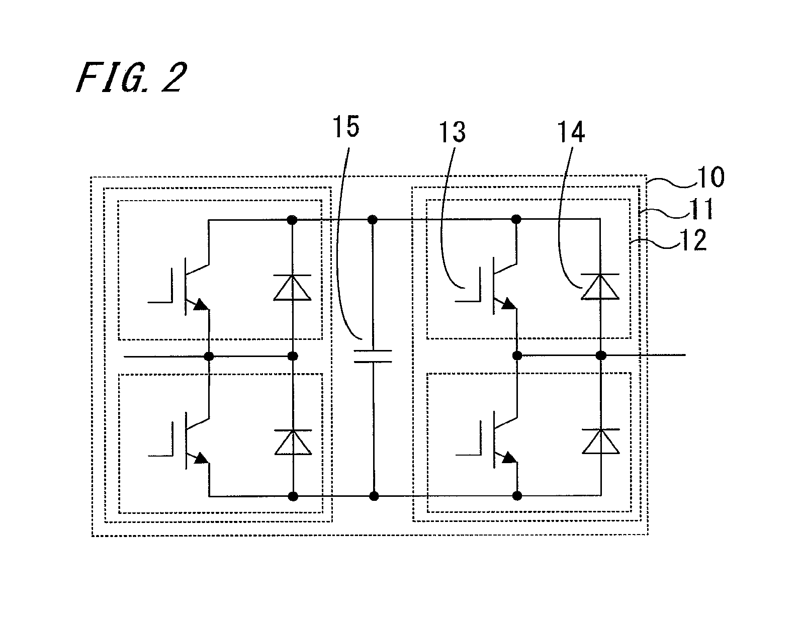
[0031]Hereinafter, the configuration and operation of an electric power conversion device 1 according to embodiment 1 of the present invention will be described on the basis of FIG. 1 which is an entire configuration diagram of the electric power conversion device, FIGS. 2 and 3 which are circuit diagrams o...
embodiment 2
[0108]An electric power conversion device in embodiment 2 has a configuration in which a function unit for controlling negative sequence current is added in the output current control unit of the electric power conversion device in embodiment 1.
[0109]Hereinafter, the configuration and operation of a controller in the output current control unit of the electric power conversion device in embodiment 2 will be described on the basis of FIG. 12 which is a configuration diagram of a controller 297, focusing on a difference from embodiment 1.
[0110]The entire configuration of the electric power conversion device in embodiment 2 is the same as that of the electric power conversion device 1 in embodiment 1. The configuration of the controller 97 in the output current control unit 90 is different, and for the purpose of discrimination from the controller 97 in embodiment 1, the controller is denoted by 297 in FIG. 12.
[0111]The converter control unit (output current control unit) in embodiment...
embodiment 3
[0117]An electric power conversion device in embodiment 3 has a configuration in which a positive sequence current control unit and a negative sequence current control unit are provided in the output current control unit.
[0118]Hereinafter, the configuration and operation of a reference voltage calculation unit in the output current control unit of the electric power conversion device in embodiment 3 will be described on the basis of FIG. 13 which is a configuration diagram of a reference voltage calculation unit 391, focusing on a difference from embodiment 1.
[0119]The entire configuration of the electric power conversion device in embodiment 3 is the same as that of the electric power conversion device 1 in embodiment 1. The configuration of the reference voltage calculation unit 391 in the output current control unit is different, and for the purpose of discrimination from the reference voltage calculation unit 91 in embodiment 1, the reference voltage calculation unit is denoted ...
PUM
 Abstract
Description
Claims
Application Information
 - R&D Engineer
- R&D Manager
- IP Professional
- Industry Leading Data Capabilities
- Powerful AI technology
- Patent DNA Extraction
Browse by: Latest US Patents, China's latest patents, Technical Efficacy Thesaurus, Application Domain, Technology Topic, Popular Technical Reports.
© 2024 PatSnap. All rights reserved.Legal|Privacy policy|Modern Slavery Act Transparency Statement|Sitemap|About US| Contact US: help@patsnap.com