Eureka AIR delivers breakthrough ideas for toughest innovation challenges, trusted by R&D personnel around the world.

Controlled porosity devices for tissue treatments, methods of use, and methods of manufacture

a porosity device and tissue treatment technology, applied in the direction of dilators, machines/engines, catheters, etc., can solve the problems of non-compliant balloons, non-compliant balloons are not suitable, and typical non-compliant balloons will not provide a feature whereby fluid is present, so as to limit the amount of visualization agents released

Active Publication Date: 2016-11-24
WL GORE & ASSOC INC
View PDF6 Cites 1 Cited by
  • Summary
  • Abstract
  • Description
  • Claims
  • Application Information

AI Technical Summary

Benefits of technology

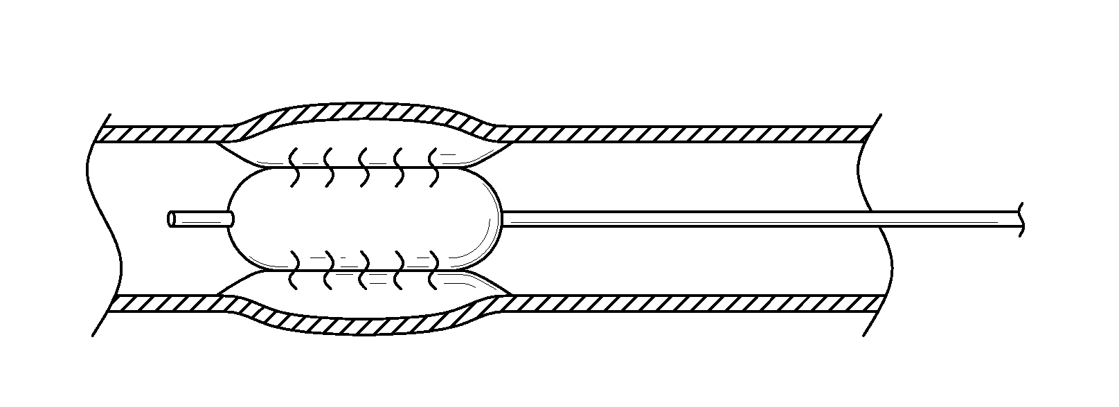
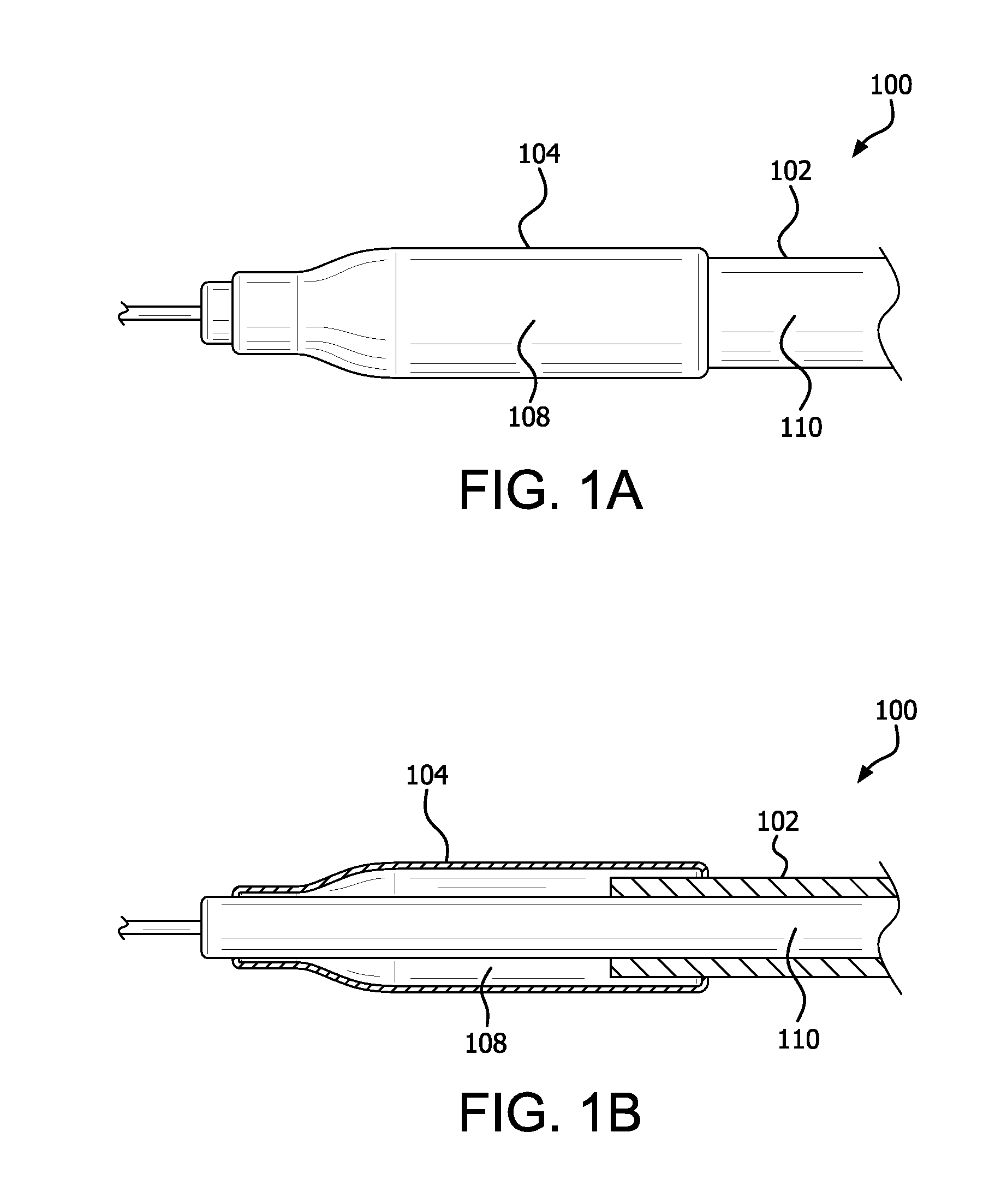
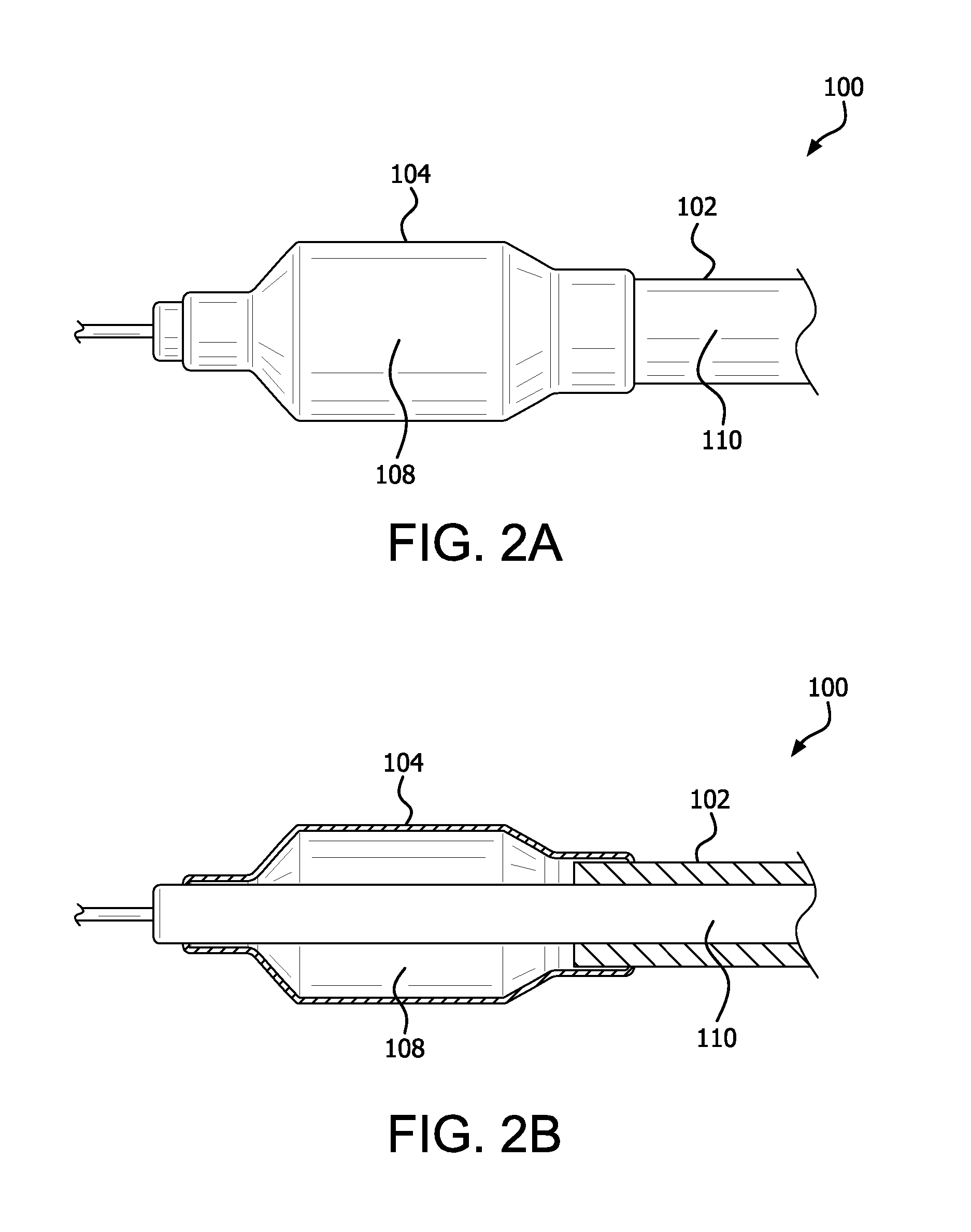
[0013]In various embodiments, an expandable balloon is provided which upon over-inflation, i.e., if the balloon's maximum “working pressure” is exceeded (its terminal pressure is reached), fluid is transferred through at least a portion of the wall of the balloon, avoiding catastrophic failure of the balloon.
[0015]In other embodiments, balloons of the present disclosure can be used to deliver a wide range of therapeutic agents. In various embodiments the balloon inflation media comprises said agents. In various embodiments, such agents are supplied in the inflation fluid, i.e., in a premixed form supplied through the proximal hub of the balloon catheter. In one embodiment, such agents are disposed in, for example, a soluble or hydratable form within the balloon structure (e.g., on the balloon catheter or inner surface of the balloon wall) and subsequently dissolved or hydrated by the inflation fluid before being transferred through the balloon wall. Alternatively, the agent can be positioned on the exterior of the balloon or within the layers of the balloon wall and is dissolved or hydrated and / or caused to be released upon fluid transfer through the wall of the balloon. In various embodiments, balloons as described herein can be used to deliver other compounds to the body, including contrast (or other visualization) agents, such as barium or iodine containing agents. In various embodiments, balloons of the present disclosure can be filled with contrast agents and used to locate side branch vessels which would normally be occluded at their ostia by a typical balloon in contact with them. In various embodiments, the balloons can be configured to release a visualization agent at only a portion of the balloon wall surface, the advantage being to limit the amount of visualization agent released into the body.
[0016]In various embodiments, balloons of the present disclosure can be used to both dilate a body cavity or lumen and deliver a fluid in the region of said dilation without the use of separate devices. In various embodiments, the balloons are constructed so as to withstand pressures of between about 8 atm and about 30 atm. In various embodiments, the balloon possesses a diameter of above about 4 mm. In various embodiments the dilation so performed is Percutaneous Transluminal Angioplasty (PTA). In one embodiment, the balloons of the present disclosure are used to occlude blood flow in a vessel with only limited or no dilation. In another embodiment, the balloons of the present disclosure are used to occlude blood flow in a vessel with only limited or no dilation, followed by delivery, through the wall of the balloon, of a therapeutic agent, for example, a sclerosing agent, for example, for vein ablation. In certain embodiments, materials for the wall of the balloon are selected to be controllably porous to liquids but allow the passage of gasses. This allows a clinician to prepare the balloon before use by expelling gasses within the balloon.

Problems solved by technology

Once a conventional, non-compliant balloon is inflated to its self-limiting diameter, the application of additional pressure can cause rupture of the balloon, creating a hazardous condition.
Therefore, a typical non-compliant balloon will not provide a feature whereby fluid can be transferred from inside the balloon, through the balloon wall, to regions outside the balloon.
Thus, for example, conventional, non-compliant balloons are not suitable for the delivery of a therapeutic agent via perfusion.
Similarly, other desirable results of perfusion cannot be realized.
As can be appreciated, there can be other problems associated with the use of conventional, non-compliant balloons.

Method used


Image

  • Controlled porosity devices for tissue treatments, methods of use, and methods of manufacture
  • Controlled porosity devices for tissue treatments, methods of use, and methods of manufacture
  • Controlled porosity devices for tissue treatments, methods of use, and methods of manufacture

Examples


example 1

Method of Making a Controlled Perfusion Balloons Comprising Three Porous Membranes as Described Herein

[0107]Four perfusion balloons in accordance with the present disclosure were constructed as follows. Expanded polytetrafluoroethylene (ePTFE) membranes made as generally described in co-assigned U.S. Pat. No. 7,306,729 entitled “POROUS PTFE MATERIALS AND ARTICLES PRODUCED THEREFROM” and described in Example 1 were obtained. The membranes were selected to possess a range of bubble point (BP) values (kPa) yet be of similar mass per unit area (grams per square meter (gsm)). The membranes exhibited the following characteristics: Membrane 1: BP=965 kPa, mass=7.4 gsm; Membrane 2: BP=800 kPa, mass=5.1 gsm; Membrane 3: BP=683 kPa, mass=4.8 gsm; Membrane 4: BP=483 kPa, mass=5.4 gsm. Each membrane was slit to a 0.64 cm width as measured across the transverse direction. These membranes served as the first porous membranes / weeping control layers of the balloons (as described herein).

[0108]An eP...


PUM

PropertyMeasurementUnit
pressureaaaaaaaaaa
pressureaaaaaaaaaa
pressureaaaaaaaaaa

Abstract

In various embodiments, a device is provided comprising a balloon configured to expand to an expanded state in response to introduction of a fluid at a first pressure, wherein the fluid perfuses through the balloon above a second pressure, the second pressure being the same or greater than the first pressure. In various embodiments, a method comprising fabricating a balloon configured to expand to an expanded state in response to introduction of a fluid at a first pressure, wherein the fluid perfuses through the balloon above a second pressure, the second pressure being at or greater than the first pressure, disposing the balloon on an elongate member having a lumen, placing the lumen in fluid communication with an interior volume of the balloon.

Description

CROSS-REFERENCE TO RELATED APPLICATION[0001]This application is a continuation of and claims priory to U.S. Non-provisional application Ser. No. 13 / 644,251 filed on Oct. 3, 2012 and entitled “Controlled Porosity Devices for Tissue Treatments, Methods of Use, and Methods of Manufacture” which claims priority to U.S. Provisional No. 61 / 544,170, filed on Oct. 6, 2011 and entitled “Controlled Porosity Devices for Tissue Treatments, Methods of Use, and Methods of Manufacture” and U.S. Provisional No. 61 / 697,0262 filed on Sep. 5, 2012 and entitled “Controlled Porosity Devices for Tissue Treatments, Methods of Use, and Methods of Manufacture,” wherein such provisional applications are hereby incorporated by reference in their entirety.FIELD OF THE DISCLOSURE[0002]The present disclosure relates, generally, to perfusion devices, such as balloons, for tissue treatments, methods of use, and methods of manufacture.BACKGROUND OF THE DISCLOSURE[0003]Balloons intended for use within a mammalian bo...

Claims


Application Information

Patent Timeline
Patent Type & Authority Applications(United States)
IPC IPC(8): A61M25/10A61L29/14A61L29/04A61M29/02A61L29/16
CPCA61M25/10A61M29/02A61M25/104A61L29/16A61M2205/36A61L29/146A61M25/1034A61M2025/105A61M2025/1075A61L29/041A61M25/1029F04C2270/0421C08L27/18A61F2/958A61F2002/9583
Inventor BACINO, JOHN E.CAMPBELL, CAREY V.CULLY, EDWARD H.TRAPP, BENJAMIN M.VONESH, MICHAEL J.
Owner WL GORE & ASSOC INC
Why Eureka
Eureka Blog
Learn More