Heat pump system for vehicle

a heat pump and vehicle technology, applied in refrigeration machines, lightening and heating apparatus, transportation and packaging, etc., can solve the problems of deteriorating heat exchange efficiency of external heat exchangers, limiting the size and enhancement of performance, and increasing power consumption due to heat exchanging efficiency degradation. , to achieve the effect of reducing power consumption and enhancing cooling performan

Active Publication Date: 2016-11-24
HANON SYST
View PDF25 Cites 15 Cited by
  • Summary
  • Abstract
  • Description
  • Claims
  • Application Information

AI Technical Summary

Benefits of technology

[0017]As described above, because the heat pump system for the vehicle includes the refrigerant-coolant heat exchanger mounted on the refrigerant circulation line of the inlet side of the external heat exchanger to exchange heat between coolant induced into the external heat exchanger and coolant circulating through electronic units of the vehicle, the heat pump system can enhance cooling performance and reduce power consumption without an increase in size of the external heat exchanger by increasing a condensation amount because refrigerant radiates heat twice while passing through the refrigerant-coolant heat exchanger and the external heat

Problems solved by technology

However, in case of the conventional heat pump system for the vehicle, in the air-conditioning mode (cooling mode), the size (thickness or an effective heat-exchanging area) of the internal heat exchanger 48 must be increased in order to enhance cooling performance and reduce power consumption, but the small space of an engine room limits increase of the size and enhancement of performance.
Moreover, in the heat pump mode (heating mode), the conventional heat pump system is limited in an amount of evaporation from the ext

Method used


Image

  • Heat pump system for vehicle
  • Heat pump system for vehicle
  • Heat pump system for vehicle

Examples


Embodiment Construction

[0026]Reference will be now made in detail to the preferred embodiment of the present invention with reference to the attached drawings.

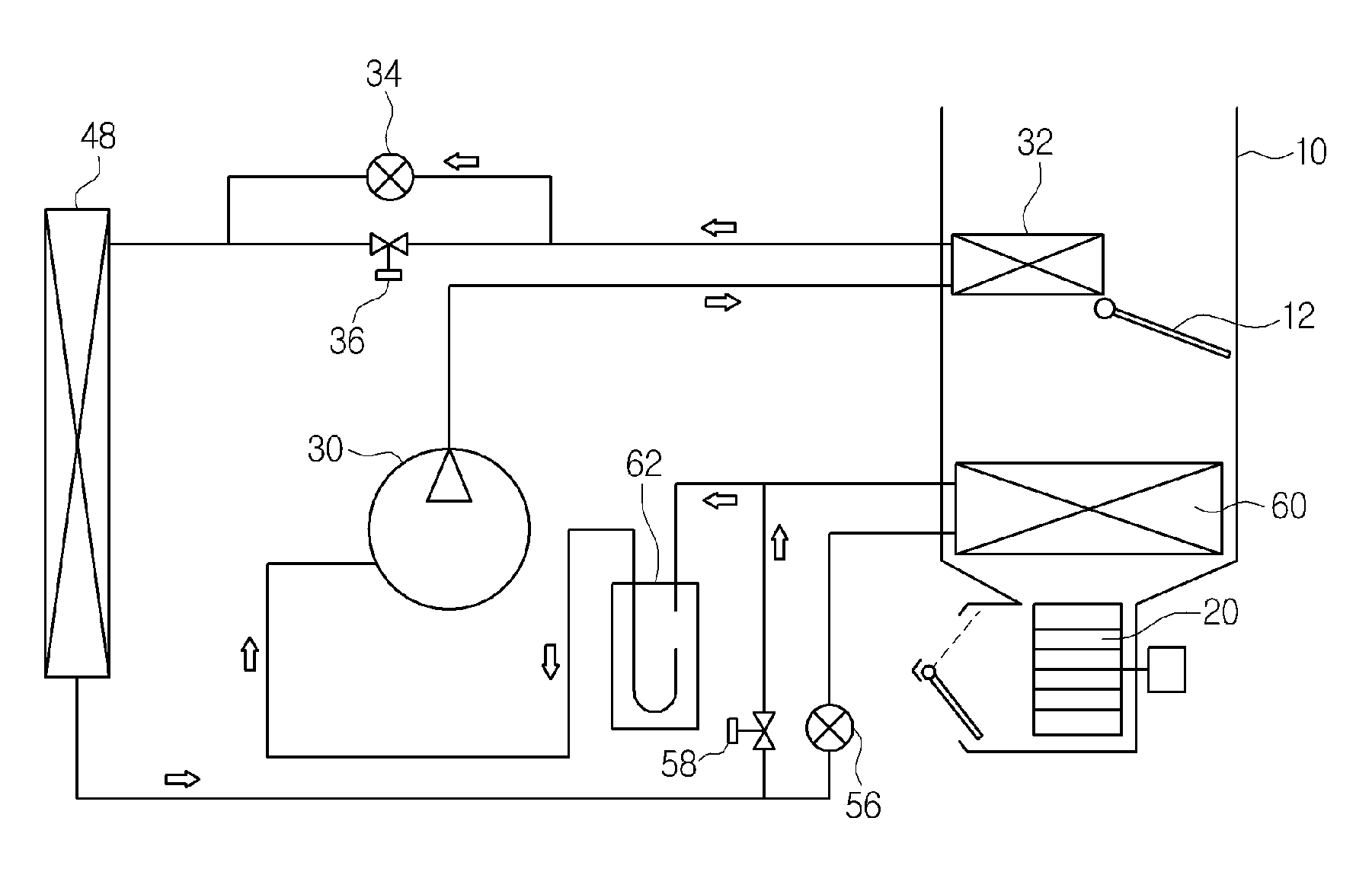
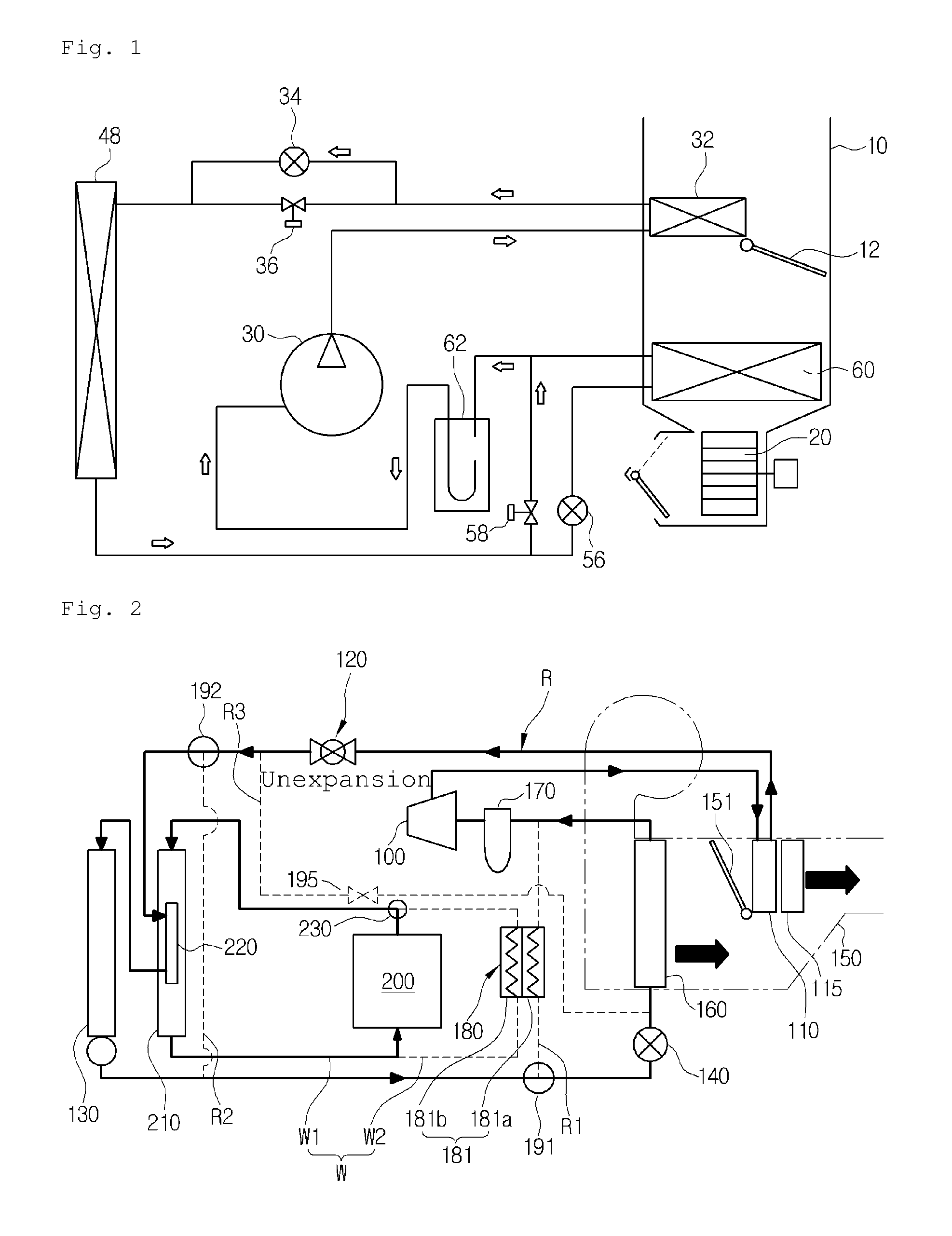
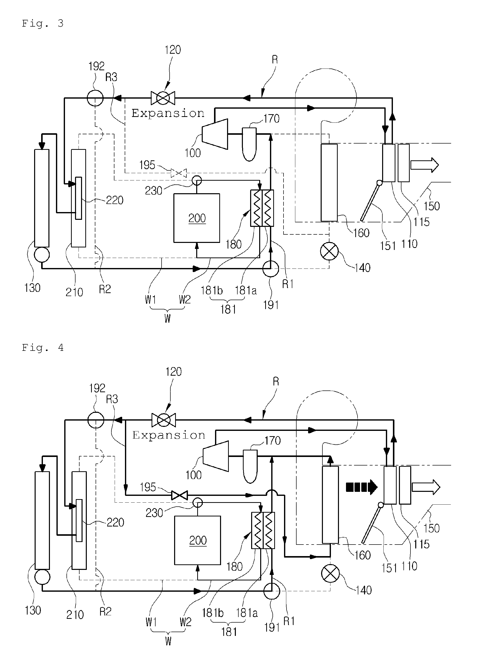
[0027]First, a heat pump system for a vehicle according to the present invention includes a compressor 100, an internal heat exchanger 110, first expansion means 120, a refrigerant-coolant heat exchanger 220, an external heat exchanger 130, second expansion means 140, and an evaporator 160 which are connected on a refrigerant circulation line (R) in order, and is preferably applied to electric vehicles or hybrid vehicles.

[0028]The refrigerant circulation line (R) is configured in such a way that refrigerant circulates through the compressor 100, the internal heat exchanger 110, the refrigerant-coolant heat exchanger 220, the external heat exchanger 130, the second expansion means 140, the evaporator 160 and the compressor 100 in an air-conditioning mode, and in such a way that the refrigerant circulates through the compressor 100, the internal heat ...


PUM


Abstract

The present invention relates to a heat pump system for a vehicle which includes a refrigerant-coolant heat exchanger mounted on a refrigerant circulation line of an inlet side of an external heat exchanger to exchange heat between coolant induced into the external heat exchanger and coolant circulating through electronic units of the vehicle, thereby enhancing cooling performance and reducing power consumption without an increase in size of the external heat exchanger by increasing a condensation amount because refrigerant radiates heat while passing through the refrigerant-coolant heat exchanger and the external heat exchanger in an air-conditioning mode and enhancing heating performance and reducing power consumption by increasing an evaporation amount because refrigerant absorbs heat while passing through the refrigerant-coolant heat exchanger, the external heat exchanger and a chiller in a heat pump mode, and increasing temperature of the refrigerant induced into the external heat exchanger to delay frosting of the external heat exchanger.

Description

TECHNICAL FIELD[0001]The present invention relates to a heat pump system for a vehicle, and more particularly, to a heat pump system for a vehicle which includes a refrigerant-coolant heat exchanger mounted on a refrigerant circulation line of an inlet side of an external heat exchanger to exchange heat between coolant induced into the external heat exchanger and coolant circulating through electronic units of the vehicle.BACKGROUND ART[0002]In general, an air conditioner for a vehicle includes a cooling system for cooling the interior of the vehicle and a heating system for heating the interior of the vehicle.[0003]At an evaporator side of a refrigerant cycle, the cooling system converts air into cold air by exchanging heat between the air passing outside an evaporator and refrigerant flowing inside the evaporator so as to cool the interior of the vehicle. At a heater core side of a coolant cycle, the heating system converts air into warm air by exchanging heat between the air pass...

Claims


Application Information

Patent Timeline
IPC IPC(8): B60H1/32B60H1/00
CPCB60H1/3205B60H1/3227B60H1/00007B60H1/00921B60H2001/00928B60H2001/00949F25B5/02F25B5/04F25B25/005B60H2001/00307B60H1/32281
Inventor CHOI, YOUNG HOKANG, SUNG HOKIM, HAK KYULEE, SEUNG HOLEE, JAE MINLEE, JUNG JAE
Owner HANON SYST
Why Eureka
Try Eureka