Patterned electrode contacts for optoelectronic devices

a technology of optoelectronic devices and contact surfaces, which is applied in the direction of light-sensitive devices, solid-state devices, electrolytic capacitors, etc., can solve the problems of increasing the space for light-sensitive materials and reducing the non-light active material content of devices, and achieve the effect of reducing diffusion limitations

Inactive Publication Date: 2016-11-24
TOYOTA MOTOR EUROPE
View PDF9 Cites 6 Cited by
  • Summary
  • Abstract
  • Description
  • Claims
  • Application Information

AI Technical Summary

Benefits of technology

[0010]In the present invention, the inventors have sought to create a basis for forming optimum micropillar structures vis-à-vis the material as well as the dimensions in order to reduce the diffusion limitation without changing the diffusion length of the carriers in a given transporting medium.

Problems solved by technology

This can reduce the non-light active material content in the device, hence increasing the space for the light sensitive material.

Method used


Image

  • Patterned electrode contacts for optoelectronic devices
  • Patterned electrode contacts for optoelectronic devices
  • Patterned electrode contacts for optoelectronic devices

Examples


Embodiment Construction

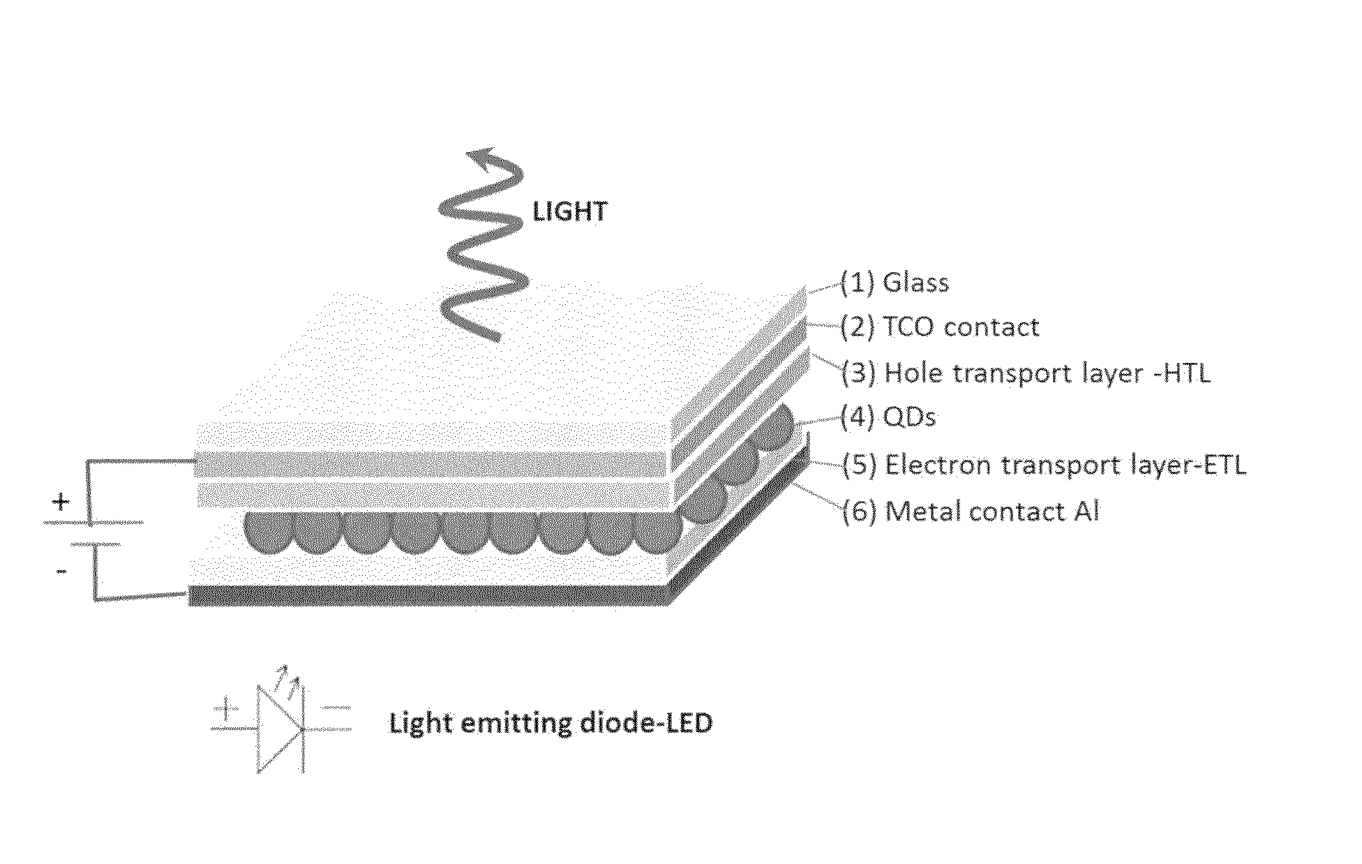
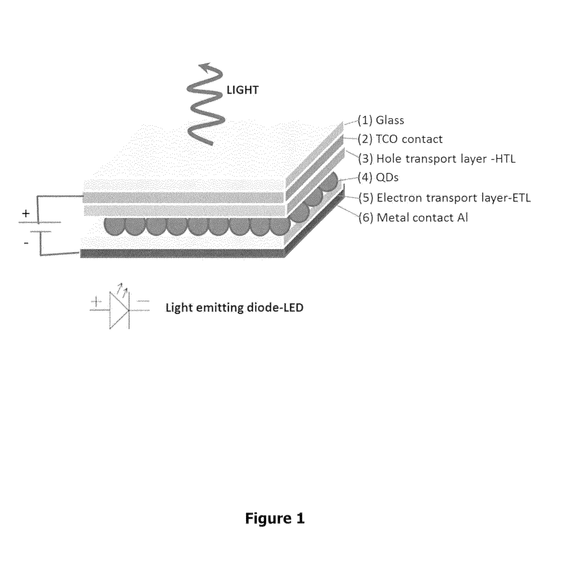
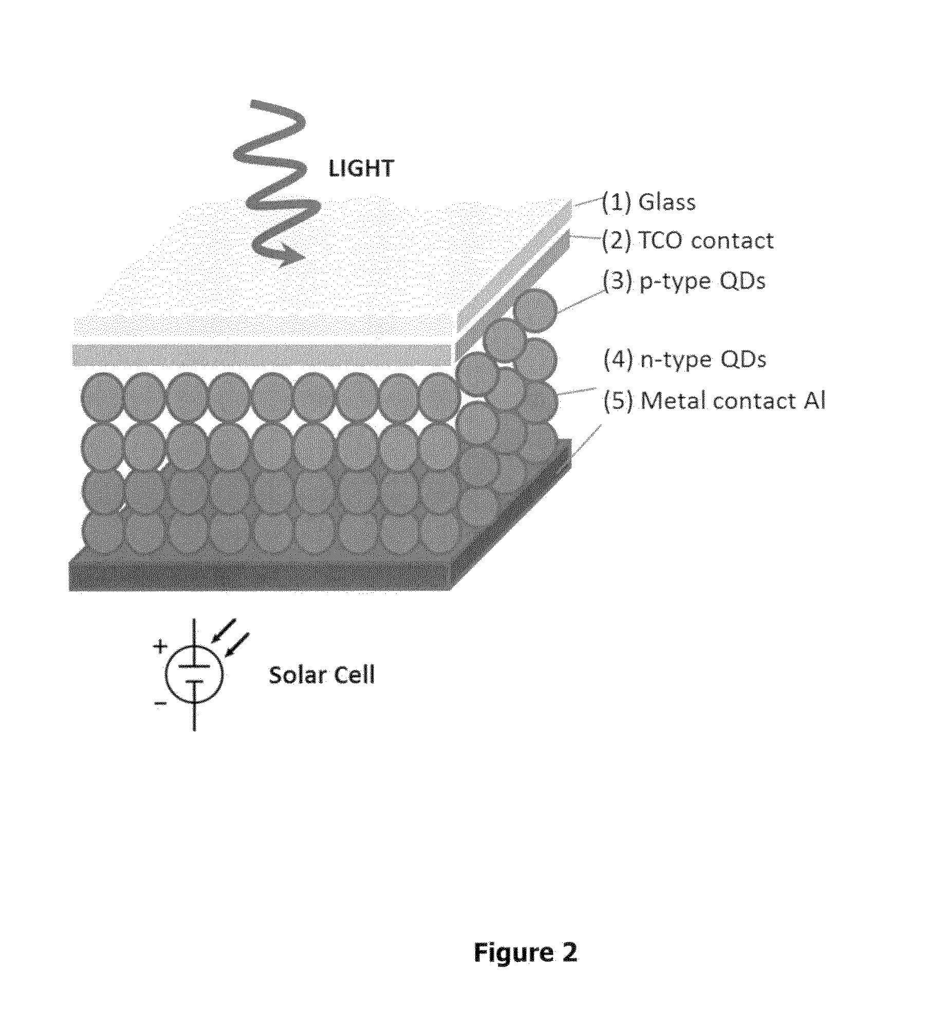
[0027]For a dye solar cell (or any sensitized solar cell), to absorb all the visible light, one typically needs a thickness of active material of a few hundred microns. However, the carriers (electron and holes) cannot travel such long distances (the maximum distance travelled is usually just a few microns or even nanometers). Electrodes should thus, as far as practicable, be close enough to point of generation of carriers due to light excitation. In thick films, e.g. a few hundred micrometers, this is impossible if the contacts are at the end. However, in the present invention, the thickness can be increased by using pillar-like electrodes. Here diffusion length is no more a major issue as the inter-pillar spacing may be chosen to be of the same order as, or even less than, the diffusion length.

[0028]In the production of a typical micropillar array according to the present invention, the collecting patterns may be prepared from transparent materials such as epoxy resins or any othe...


PUM


Abstract

A micropillar array structure includes a substrate; and an array of micropillars provided on a surface of the substrate, wherein the micropillars are substantially transparent to light, and the height of micropillars is at most 500 μm. The micropillar array structures can be used in optoelectronic devices such as solar cells.

Description

FIELD OF THE INVENTION[0001]The present invention relates to patterned electrode contact surfaces that can be used in various optoelectronic devices.BACKGROUND TO THE INVENTION[0002]Common optoelectronic devices include sensors and solar cells. As regards solar cells for practical use, one may consider that in the “first generation” of devices, thick single crystalline forms of silicon have been used.[0003]By differential doping to create a p-n junction, photoelectric conversion efficiencies of 30% are theoretically possible, and some systems developed show efficiencies up to 25%. In a “second generation” of products that have recently become available, thinner films (with thicknesses typically in the 150 to 180 μm range) have been developed, which may use silicon, or other semiconducting material such as cadmium telluride (CdTe). Similar efficiencies are potentially available. The theoretical limit is identical for thin films. Another example of 2nd generation product is a dye-sens...

Claims


Application Information

Patent Timeline
Patent Type & Authority Applications(United States)
IPC IPC(8): H01G9/20H01L51/44H01L51/42
CPCH01G9/209H01L51/447H01L51/426Y02E10/542Y02E10/549H10K30/35H10K30/87H10K50/80
Inventor KINGE, SACHINCANOVAS DIAZ, ENRIQUEBONN, MISCHA
Owner TOYOTA MOTOR EUROPE
Why Eureka
Try Eureka