Wireless transmission device, wireless reception device, wireless communication system, and wireless communication method

a wireless reception device and wireless communication technology, applied in the direction of transmission, electrical equipment, etc., can solve the problems of high fluctuation of transmission characteristics, high risk of fading, and high probability of low c/n operation, and achieve stable clock synchronization

Active Publication Date: 2016-11-24
NEC CORP
View PDF7 Cites 2 Cited by
  • Summary
  • Abstract
  • Description
  • Claims
  • Application Information

AI Technical Summary

Benefits of technology

[0023]According to the above-described aspects of the present invention, it is possible to ensure stable

Problems solved by technology

On the other hand, in the non-line-of-sight (NLOS) communication, in which there are obstacles between the transmitting and receiving sides, since no direct waves arrive at the receiving side and there is no difference in the intensities of incoming waves through respective paths, the transmission characteristics fluctuate a lot due to the mutual interference between the incoming waves through the respective paths.
In non-line-of-sight communication, down fading is likely to occur at low C/N operation.
In this case, it is likely to get out clock sy

Method used


Image

  • Wireless transmission device, wireless reception device, wireless communication system, and wireless communication method
  • Wireless transmission device, wireless reception device, wireless communication system, and wireless communication method
  • Wireless transmission device, wireless reception device, wireless communication system, and wireless communication method

Examples


first exemplary embodiment

A first Exemplary Embodiment

[0039]A first exemplary embodiment of the present invention will be described. FIG. 10A illustrates a block diagram of a wireless transmission device, and FIG. 10B illustrates a block diagram of a wireless receiving device, in accordance with the present exemplary embodiment.

[0040]In FIG. 10A, a wireless transmission device 1 includes a clock generation unit 11, a spreading unit 12, an adder 13, and a transmission unit 14.

[0041]The clock generation unit 11 generates a clock signal (CLK). The spreading unit 12 multiplies the clock signal by a spreading code and generates a spread-spectrum clock signal (spread-spectrum CLK) whose spectrum is made to spread. The adder 13 superimposes an information signal to be transmitted on the spread-spectrum clock signal. The transmission unit 14 performs frequency conversion (up-conversion) on the output from the adder 13 and transmits an up-converted signal by wireless.

[0042]In FIG. 10B, a wireless receiving device 2 i...

second exemplary embodiment

A Second Exemplary Embodiment

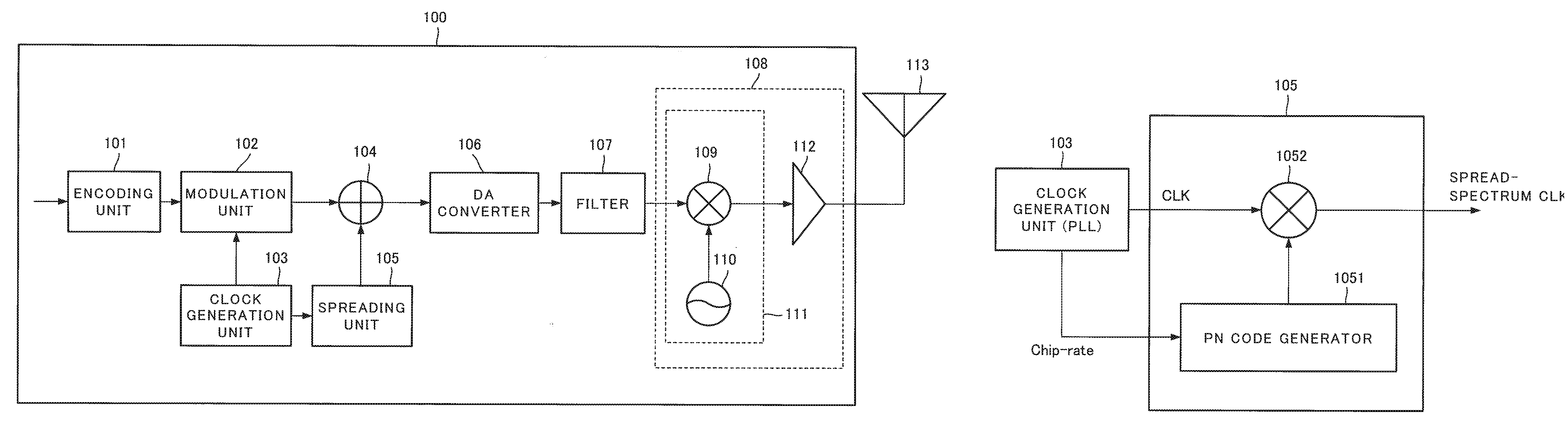
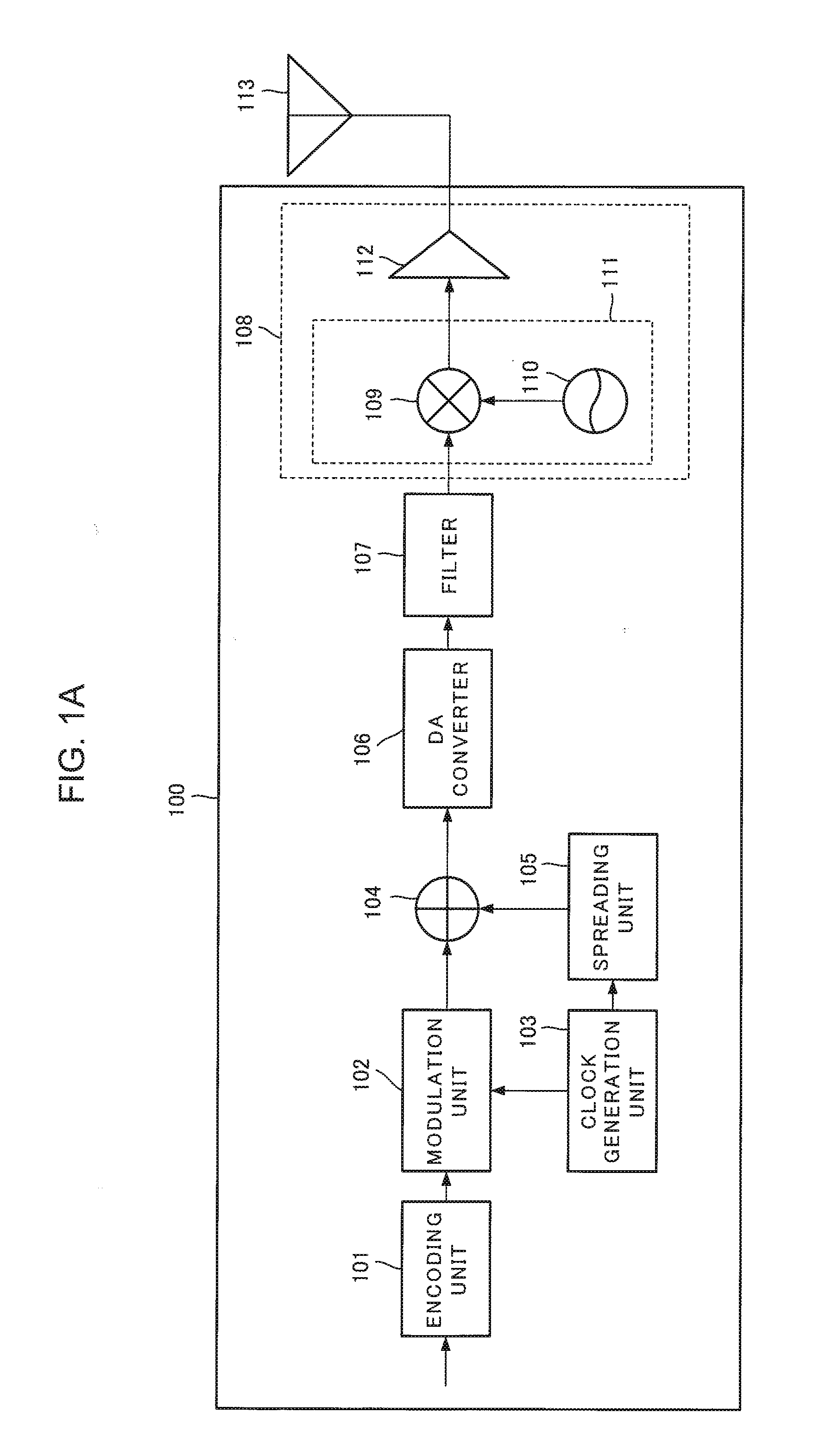
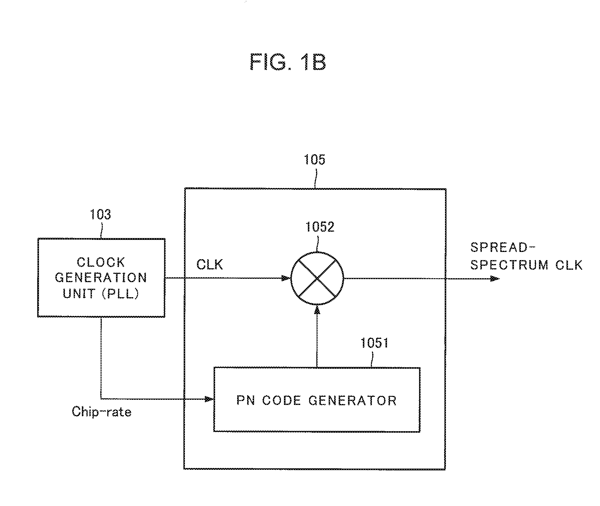
[0048]A second exemplary embodiment will be described. First, a wireless transmission device will be described. FIG. 1A illustrates a block diagram of a wireless transmission device in accordance with the present exemplary embodiment. In FIG. 1A, a wireless transmission device 100 includes an encoding unit 101, a modulation unit 102, a clock generation unit 103, an adder 104, a spreading unit 105, a DA (digital to analog) converter 106, a filter 107, a transmission unit 108, and a transmitting antenna 113.

[0049]The encoding unit 101 encodes an inputted data signal using an error-correcting code, for example, and supplies the encoded signal to the modulation unit 102.

[0050]The clock generation unit 103 generates a clock signal and supplies the generated clock signal to the modulation unit 102 and the spreading unit 105. The clock generation unit 103 in accordance with the present exemplary embodiment includes a phase locked loop (PLL), for example, and ou...

third exemplary embodiment

A Third Exemplary Embodiment

[0083]A third exemplary embodiment will be described. FIG. 8 and FIG. 9 illustrate block configuration diagrams of a wireless transmission device 100C and a wireless receiving device 200B, respectively, which are applied to the non-line-of-sight communication by fourfold diversity using two antennas (space diversity) and two frequencies (frequency diversity).

[0084]The branch number L of the space diversity is not limited to two, and the branch number L of the frequency diversity is not limited to two. However, since L-fold bandwidth is required for the branch number L of the frequency diversity, the frequency efficiency is down, and L-fold transmission power is required.

[0085]In FIG. 8, only a single line is illustrated with respect to an adder 104, a DA converter 106, and a filter 107. In FIG. 9, although each of receiving units 202a to 202d performs wireless quadrature demodulation and outputs intermediate frequency (IF) signals having each of I and Q c...


PUM


Abstract

Stable clock synchronization is ensured even under a multi fading environment such as the non-line-of-sight communication.
On a transmission side, multiplying a clock signal by a spreading code, a spread-spectrum clock signal is generated whose spectrum being made to spread; frequency conversion is performed on a signal obtained by superimposing an information signal on the spread-spectrum clock signal and a radio signal is transmitted by wireless. On the other hand, on a receiving side, the radio signal is received, frequency conversion is performed on the radio signal, and a frequency-converted radio signal is divided into two lines. A clock signal extracted by performing spectrum despreading on one of divided radio signals by multiplying a spreading code; and clock synchronization is performed on other one of the divided radio signals using the clock signal having been extracted.

Description

TECHNICAL FIELD[0001]The present invention relates to a wireless transmission device, a wireless receiving device, a wireless communication system, and a wireless communication method.BACKGROUND ART[0002]In wireless communications, the reception level (electric field intensity) fluctuates because incoming waves interfere mutually which have passed through a plurality of different paths (multipath) due to reflection, refraction, scattering, and the like caused by structures, natural terrains, and the like (multipath fading). In the line-of-sight communication, since the intensity of incoming waves is relatively low that arrive through paths other than those for direct waves, and that are included in radio waves arriving at the receiving side, there is less fluctuation of transmission characteristics due to a positional relation and the like.[0003]On the other hand, in the non-line-of-sight (NLOS) communication, in which there are obstacles between the transmitting and receiving sides...

Claims


Application Information

Patent Timeline
IPC IPC(8): H04B1/7073
CPCH04B1/7073
Inventor MURAI, TAKAYUKI
Owner NEC CORP
Why Eureka
Try Eureka