

Hydrogen sulfide imaging system
a hydrogen sulfide and imaging system technology, applied in the field of system and method of detecting spectral signatures of hydrogen sulfide, can solve problems such as human danger
- Summary
- Abstract
- Description
- Claims
- Application Information
AI Technical Summary
Benefits of technology
Problems solved by technology
Method used
Image


Examples
embodiment 300
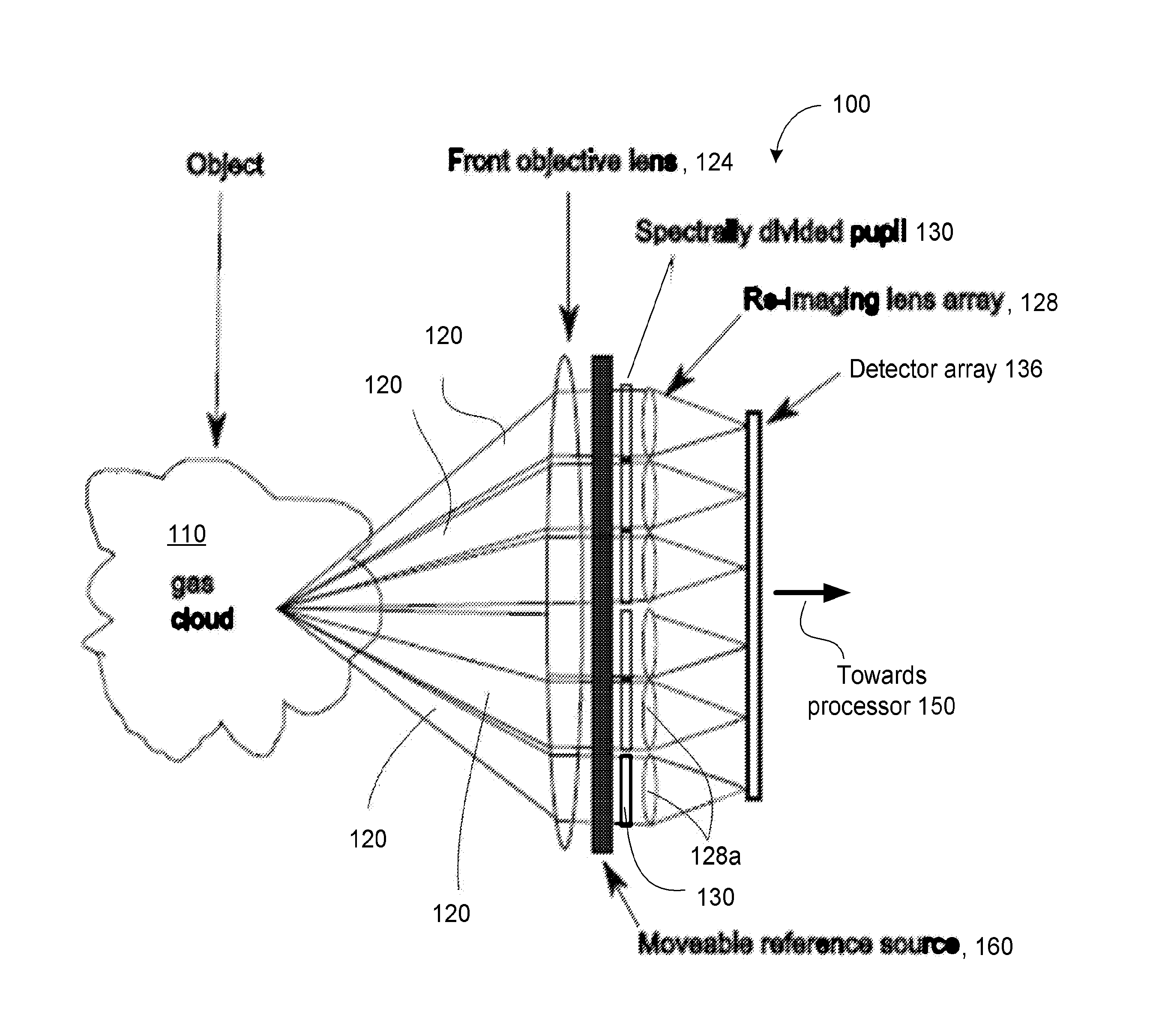
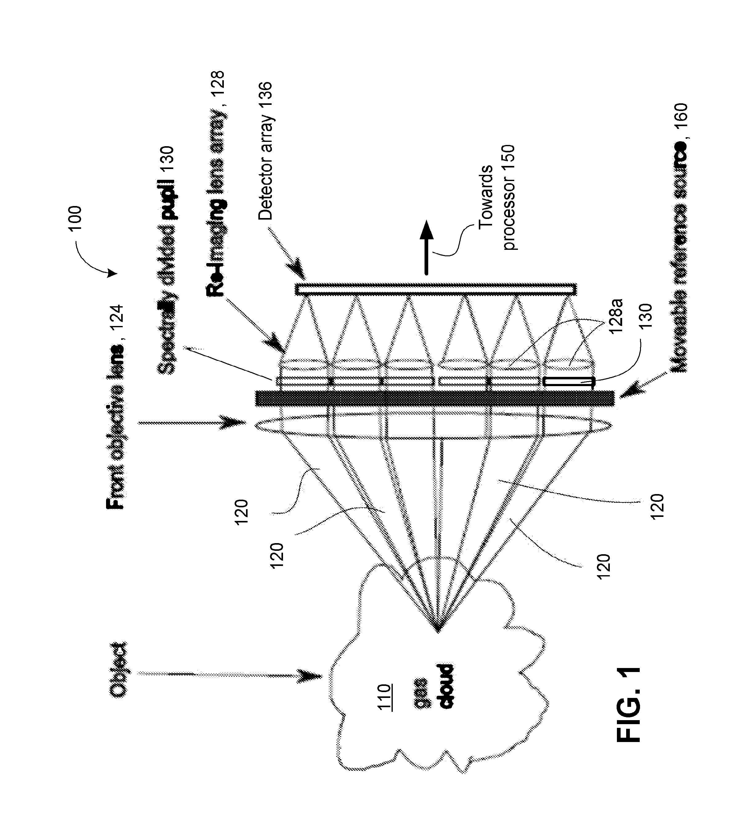
[0449]FIG. 3A illustrates schematically an embodiment 300 of the imaging system in which the number of the front objective lenses 324a in the lens array 324, the number of re-imaging lenses 128a in the lens array 128, and the number of FPAs 336 are the same. So configured, each combination of respectively corresponding front objective lens 324, re-imaging lens 128a, and FPAs 336 constitutes an individual imaging channel. Such a channel is associated with acquisition of the IR light transmitted from the object 110 through an individual filter element of the array of optical filters 130. A field reference 338 of the system 300 is configured to have a uniform temperature across its surface and be characterized by a predetermined spectral curve of radiation emanating therefrom. In various implementations, the field reference 338 can be used as a calibration target to assist in calibrating or maintaining calibration of the FPA. Accordingly, in various implementations, the field reference...
embodiment 400
[0473]As already discussed, and in reference to FIGS. 1 through 4, the field-reference apertures may be disposed in an object space or image space of the optical system, and dimensioned to block a particular portion of the IR radiation received from the object. In various implementations, the field-reference aperture, the opening of which can be substantially similar in shape to the boundary of the filter array (for example, and in reference to a filter array of FIGS. 3B, 5B—e.g., rectangular). The field-reference aperture can be placed in front of the objective lens (124, 224, 324, 424) at a distance that is at least several times (in one implementation—at least five times) larger than the focal length of the lens such that the field-reference aperture is placed closer to the object. Placing the field-reference aperture closer to the object can reduce the blurriness of the image. In the embodiment 400 of FIG. 4, the field-reference aperture can be placed within the depth of focus o...
embodiment 1000
[0506]FIG. 10A illustrates schematically a related embodiment 1000 of the imaging system, in which one or more mirrors M0A, M11A and M0B, M11B are placed within the fields of view of one or more cameras 0, . . . , 11, partially blocking the field of view. The cameras 0, . . . , 11 are arranged to form an outer ring of cameras including cameras 0, 1, 2, 3, 7, 11, 10, 9, 8 and 4 surrounding the central cameras 5 and 6. In various implementations, the FOV of the central cameras 5 and 6 can be less than or equal to the FOV of the outer ring of cameras 0, 1, 2, 3, 7, 11, 10, 9, 8 and 4. In such implementations, the one or more mirrors M0A, M11A and M0B, M11B can be placed outside the central FOV of the cameras 5 and 6 and is placed in a peripheral FOV of the cameras outer ring of cameras 0, 1, 2, 3, 7, 11, 10, 9, 8 and 4 which does not overlap with the central FOV of the cameras 5 and 6 such that the reference sources A and B are not imaged by the cameras 5 and 6. In various implementati...
PUM
 Abstract
Description
Claims
Application Information