Apparatus for generating image and method thereof

a technology of analogous and dynamic range, applied in the field of analogous metal oxide semiconductor (cmos) image sensors, can solve the problems of difficult hardware implementation, inability to accurately capture images, and difficulty in generating images, so as to reduce noise, effectively generate high dynamic range images, and reduce complexity

Active Publication Date: 2016-12-01
SK HYNIX INC
View PDF6 Cites 28 Cited by
  • Summary
  • Abstract
  • Description
  • Claims
  • Application Information

AI Technical Summary

Benefits of technology

[0017]When a motion and saturation area is detected by the motion and saturation detection unit, the radiance map generation unit may replace the long exposure block with the L short exposure block and perform noise filtering for an L short exposure image, and when the motion and saturation area is not detected by the motion and saturation detection unit, the radiance map generation unit may perform a weighted sum for the long exposure block and a result of the guided filter, and eliminate noise.
[0030]Furthermore, since the present invention uses luminance of input, it is possible to significantly reduce the memory resources consumed.

Problems solved by technology

And, when one or more of the red, green, and blue colors are in a saturated state, the image sensor is unable to accurately capture the image.
Since conventional high dynamic range (HDR) algorithms simply use a weighted sum scheme, noise may occur when synthesizing images.
Furthermore, since the conventional high dynamic range algorithms use local tone mapping to preserve local tone, which is highly complex, it is difficult to implement with hardware.
In addition, the conventional high dynamic range algorithm uses a lot of memory to incorporate luminance at the time of tone mapping.

Method used


Image

  • Apparatus for generating image and method thereof
  • Apparatus for generating image and method thereof
  • Apparatus for generating image and method thereof

Examples


Embodiment Construction

[0037]Various embodiments will be described below in more detail with reference to the accompanying drawings. The present invention may, however, be embodied in different forms and should not be construed as limited to the embodiments set forth herein. Rather, these embodiments are provided so that this disclosure will be thorough and complete, and will fully convey the scope of the present invention to those skilled in the art. Throughout the disclosure, like reference numerals refer to like parts throughout the various figures and embodiments of the present invention.

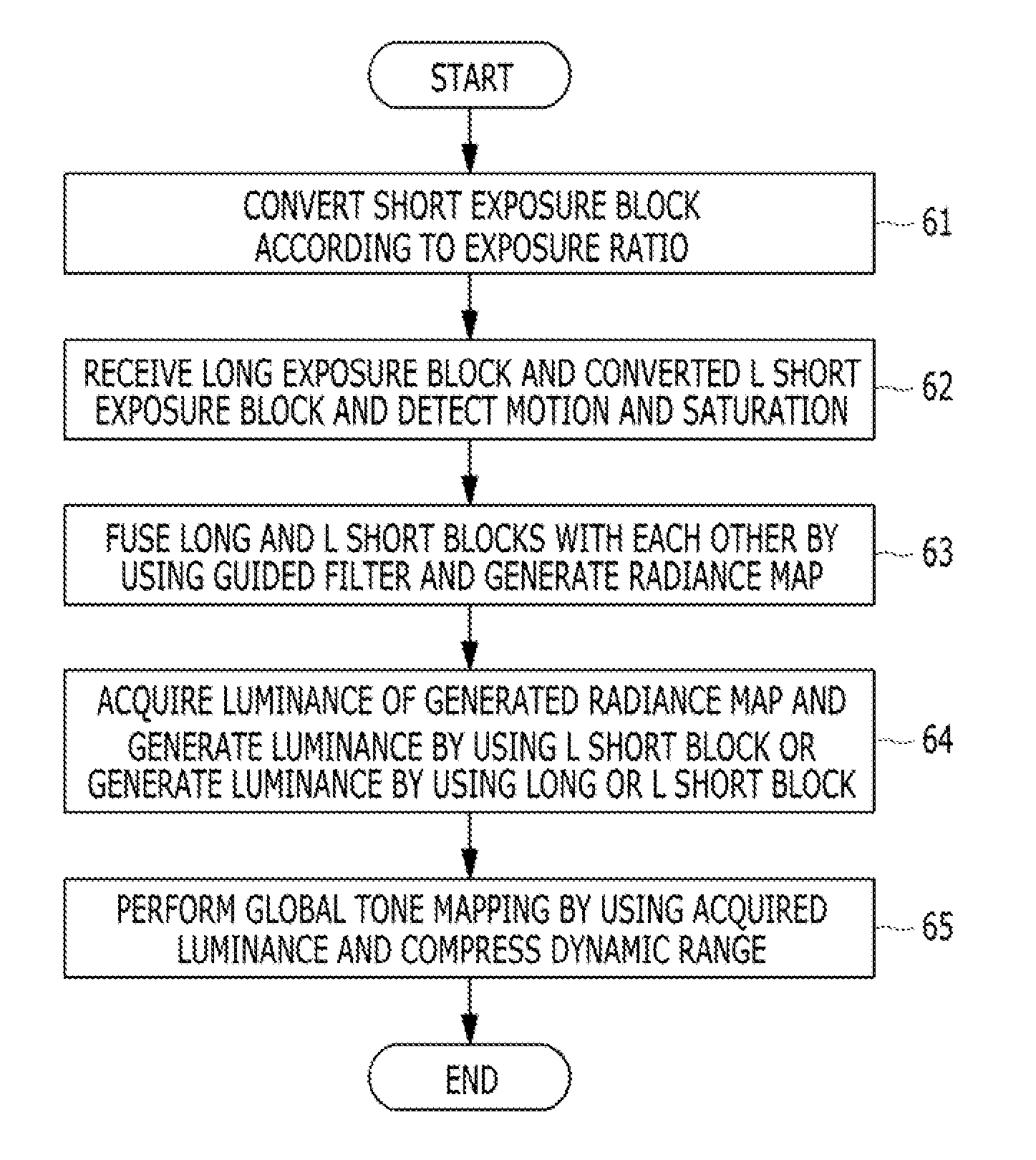
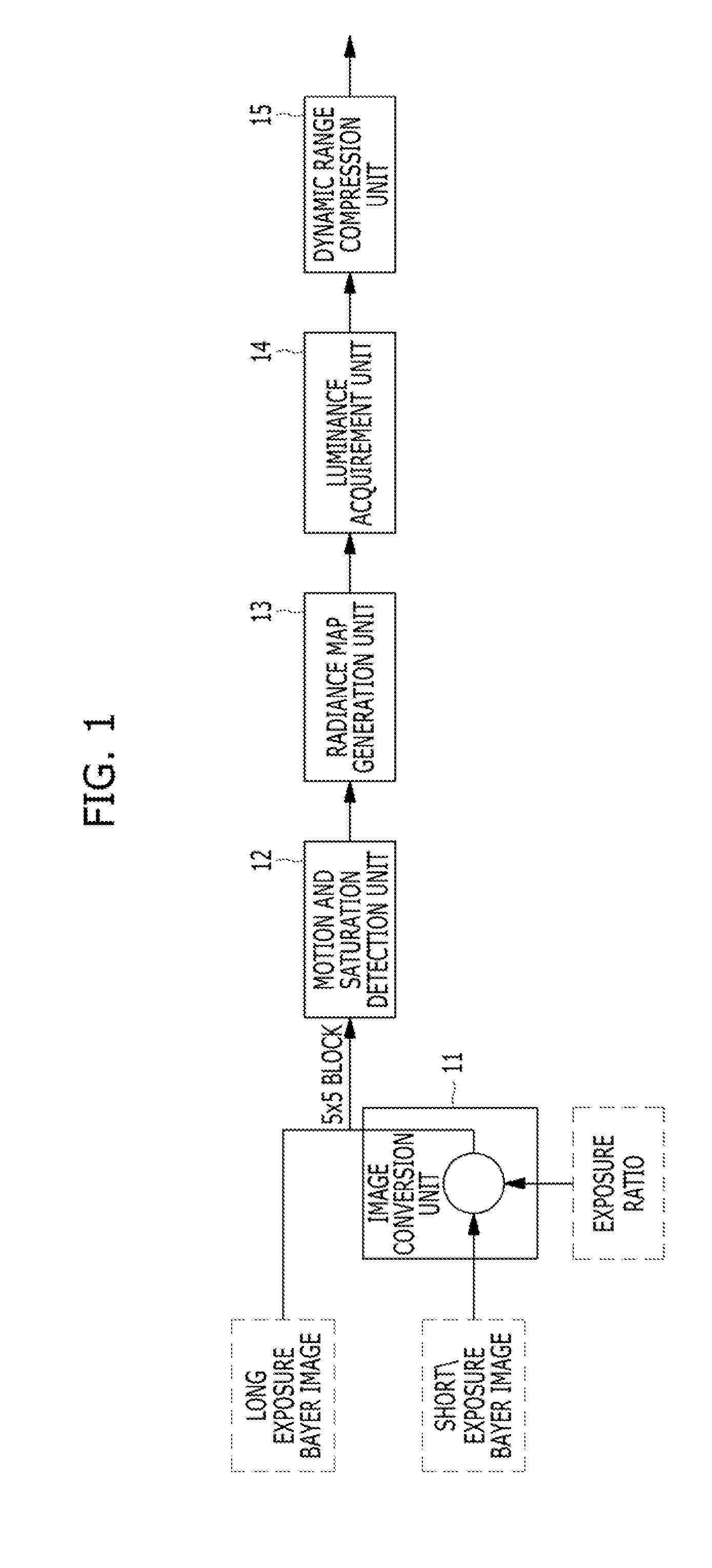
[0038]FIG. 1 is a block diagram illustrating a low complexity high dynamic range image generation apparatus in accordance with an embodiment of the present invention.

[0039]As illustrated in FIG. 1, the low complexity high dynamic range image generation apparatus includes an image conversion unit 11 for converting a short exposure block according to an exposure ratio, a motion and saturation detection unit 12 for recei...


PUM


Abstract

An apparatus includes an image conversion unit suitable for converting a short exposure block according to an exposure ratio; a motion and saturation detection unit suitable for receiving a long exposure block and an L short exposure block converted by the image conversion unit, and detecting motion and saturation; a radiance map generation unit suitable for fusing the long and L short exposure blocks using a guided filter, and generating a radiance map; a luminance acquirement unit suitable for acquiring luminance of the radiance map, and generating luminance using the L short exposure block or respectively generating luminance using the long and L short exposure blocks; and a dynamic range compression unit suitable for performing global tone mapping using the luminance acquired by the luminance acquirement unit, and compressing a dynamic range.

Description

CROSS-REFERENCE TO RELATED APPLICATIONS[0001]The present application claims priority of Korean Patent Application No. 10-2015-0072841, filed on May 26, 2015, which is incorporated herein by reference in its entirety.BACKGROUND[0002]1. Field[0003]Exemplary embodiments of the present invention relate to a Complementary Metal Oxide Semiconductor (CMOS) image sensor (CIS), and more particularly, to an apparatus for generating a high dynamic range image and a method thereof.[0004]2. Description of the Related Art[0005]Dynamic range is one of the important criteria for judging the quality of an image sensor. Dynamic range is the maximum range in which an input signal may be processed without distortion. With wide dynamic range, it is possible to acquire a quality image even with great variance in brightness. Conventional color image sensors are known to have narrow dynamic ranges. And, when one or more of the red, green, and blue colors are in a saturated state, the image sensor is unable...

Claims


Application Information

Patent Timeline
Patent Type & Authority Applications(United States)
IPC IPC(8): H04N5/235G06T7/60G06T7/20
CPCH04N5/2355G06T7/60G06T7/20G06T5/008G06T5/50G06T2207/10016G06T2207/10144G06T2207/20021G06T2207/20221H04N23/6811H04N23/741
Inventor MIN, CHANG-KIKIM, NAM-HYUNJUNG, SE-MYOUNG
Owner SK HYNIX INC
Why Eureka
Try Eureka