A backlight unit and a display device

a backlight unit and display device technology, applied in the field of display technology, can solve the problems of backlight thickness and not conforming to the design trend of ultra-thin display, and achieve the effect of facilitating thinness design and reducing display thickness

Active Publication Date: 2016-12-08
BOE TECH GRP CO LTD
View PDF0 Cites 5 Cited by
  • Summary
  • Abstract
  • Description
  • Claims
  • Application Information

AI Technical Summary

Benefits of technology

[0005]In order to overcome the above problem and reduce the thickness of the display so as to facilitate the thinness design, the present invention provides an improved backlight unit and a display device.

Problems solved by technology

However, in this way, the thickness of the light guide plate 11 will be increased, thereby enabling the thickness of the backlight unit to be enlarged, which does not conform to the design trend of ultra-thinness of the display.

Method used


Image

  • A backlight unit and a display device
  • A backlight unit and a display device
  • A backlight unit and a display device

Examples


first embodiment

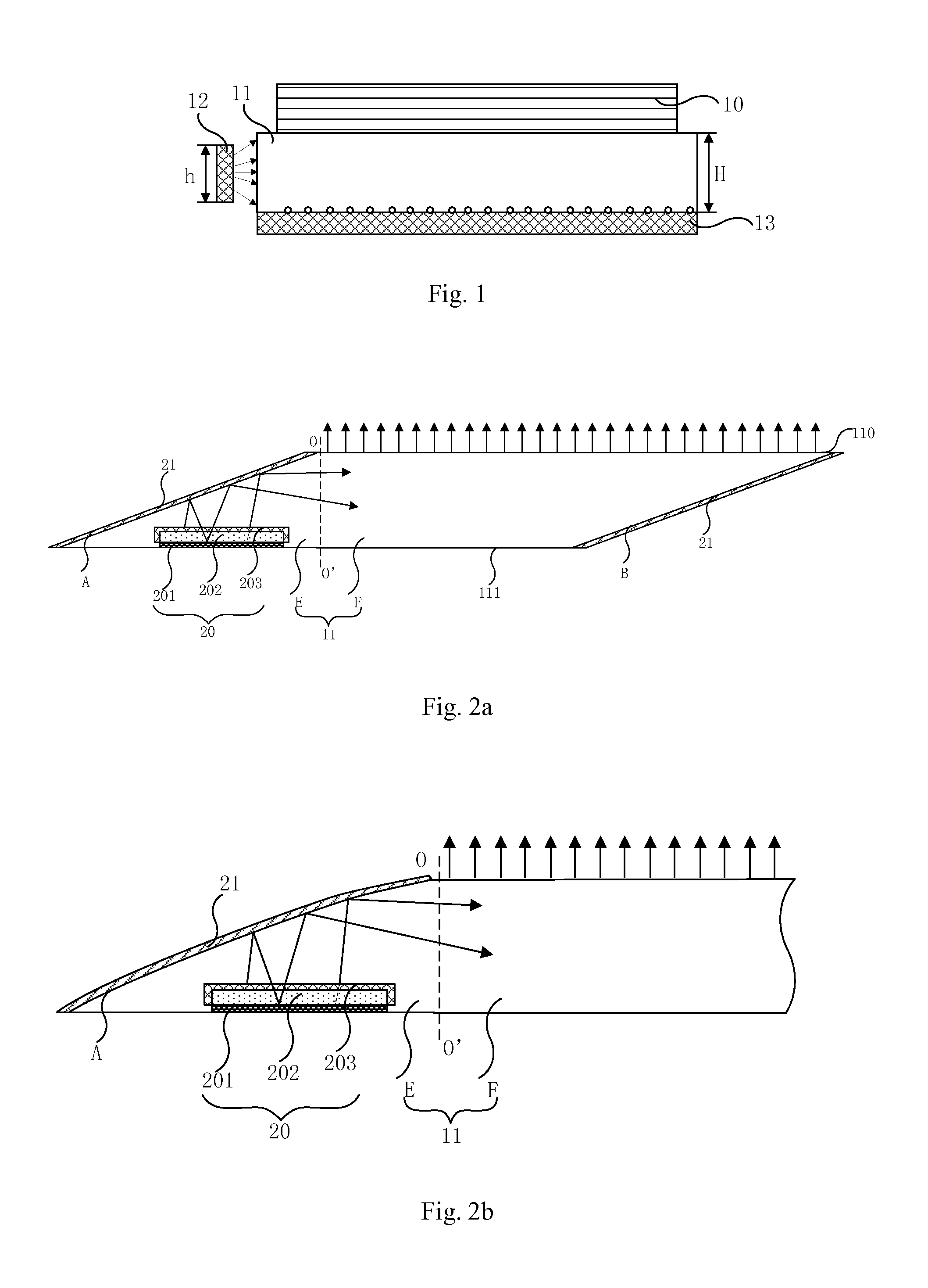
[0034]FIGS. 2a and 2b show a structural schematic view and a local structural view of a backlight unit according to the present invention respectively. As shown in FIG. 2a, the backlight unit comprises:

[0035]a light guide plate 11 comprising a first inclined side A and an upper bottom surface 110 and a lower bottom surface 111 parallel with each other, wherein the angle between the first inclined side A and the lower bottom surface 111 is a sharp angle;

[0036]a light emitting element 20 arranged below the first inclined side A;

[0037]a first reflector 21 arranged on a surface of the first inclined side A.

[0038]In the backlight unit as shown in FIG. 2a, a corresponding part below the first inclined side A within the light guide plate is used for arranging a light emitting element, and then, the other part may be used for implementing the light guide function. In addition, since the angle between the first inclined side A and the lower bottom surface 111 is a sharp angle, the angle betw...

second embodiment

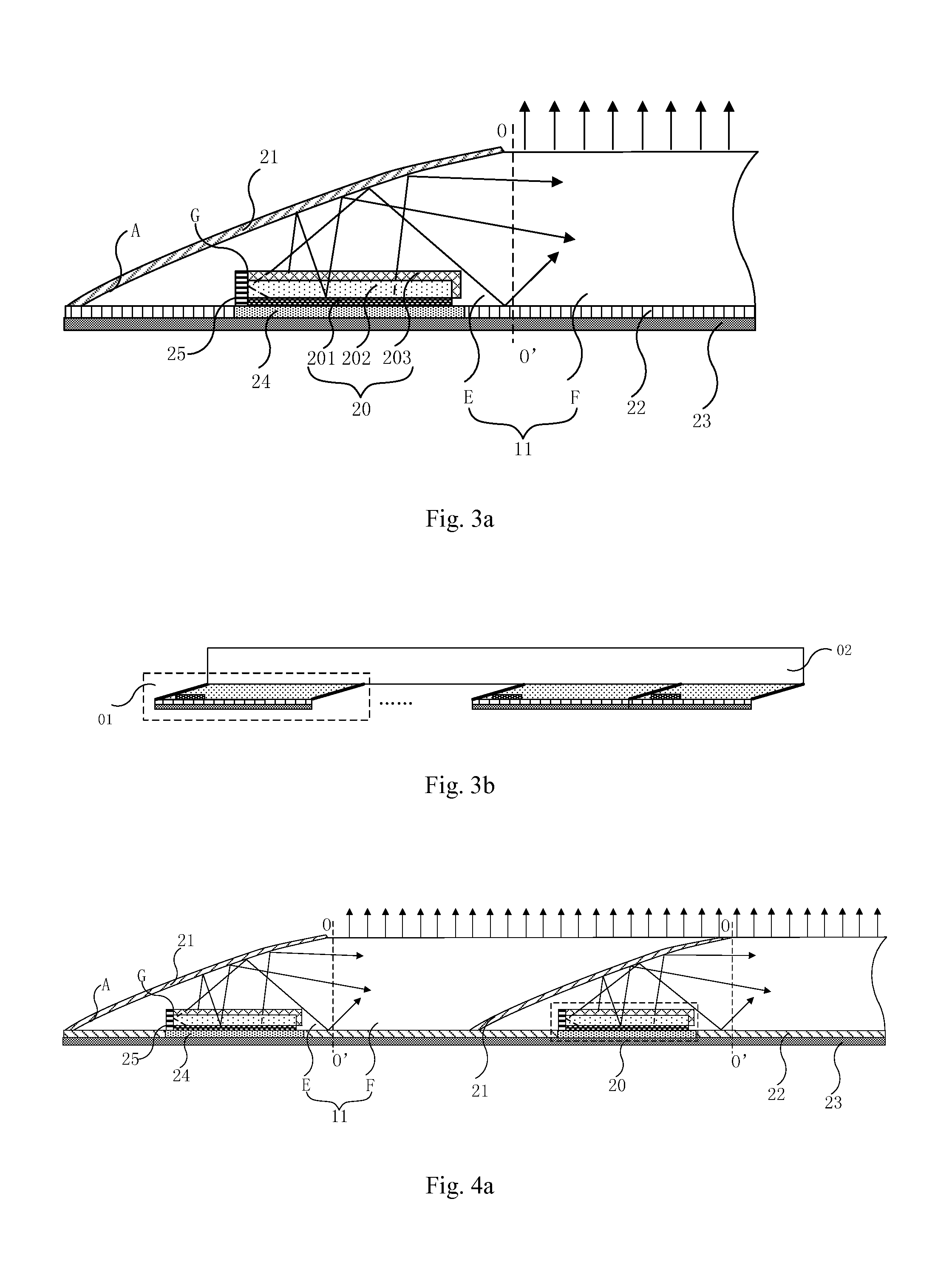
[0045]FIG. 3a shows a local structural schematic view of a backlight unit according to the present invention. As shown in FIG. 3a, the backlight unit may further comprise a second reflector 22 arranged on the lower bottom surface 111 of the light guide plate 11. Through the second reflector 22, the light reflected by the first reflector 21 to the lower bottom surface 11 of the light guide plate 11 can be reflected again, to enable it to be incident into the light guide area F of the light guide plate 11, thereby increasing utilization rate of the light.

[0046]In the backlight unit according to the second embodiment of the present invention as shown in FIG. 3a, the backlight unit may further comprise a heat sink 23 arranged at the underside of the second reflector 22, for dissipating the heat generated by the light emitting element 20 in the luminescent phase, so as to prevent the backlight unit from generating adverse impact to the liquid crystal layer or the control circuit in the d...

third embodiment

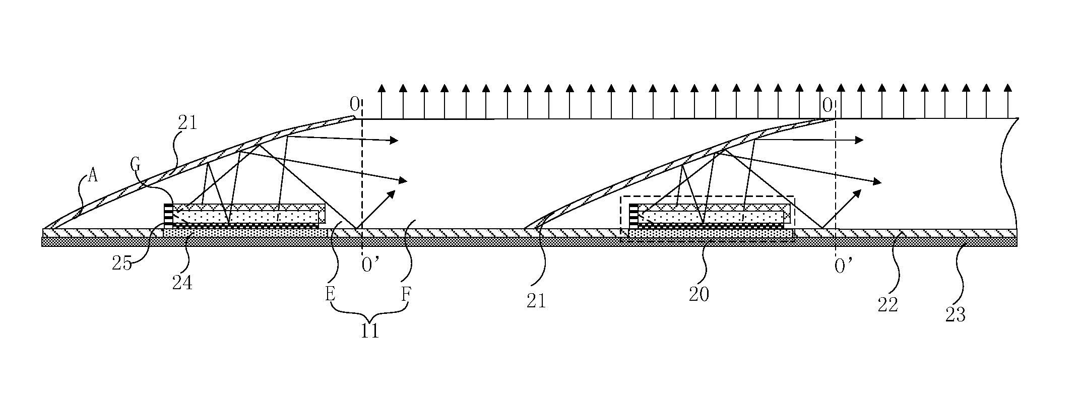
[0051]FIG. 4a shows a local structural schematic view of a backlight unit according to the present invention. As shown in FIG. 4a, the backlight unit may comprise at least two mutually spliced light guide plates 11, the first reflector 21 is clamped between the second inclined side B of one of two adjacent light guide plates 11 and the first inclined side A of the other light guide plate 11.

[0052]Wherein the first reflector 21 clamped between the two adjacent light guide plates 11 may be a double side reflector. Thus the double side reflector can not only reflect again the light reflected by the first reflector 21 in the light guide plate 11 located at the left side to the lower bottom surface 111 of the light guide plate 11, to enable it to be incident into the light guide area F of the left light guide plate 11, thereby increasing utilization rate of the light, but also can reflect the light emitted by the light emitting element 20 in the right light guide plate 11 into the light ...


PUM


Abstract

The present invention relates to the field of display technology, particularly to a backlight unit and a display device. The backlight unit according to the present invention comprises: a light guide plate, the light guide plate comprising a first inclined side and an upper bottom surface and a lower bottom surface parallel with each other, wherein the angle between the first inclined side and the lower bottom surface is a sharp angle; a light emitting element arranged below the first inclined side; and a first reflector arranged on a surface of the first inclined side of the light guide plate. Compared with the prior art, the thickness of such a backlight unit can be kept relatively small, which facilitates lighter and thinner design of the liquid crystal display.

Description

FIELD OF THE INVENTION[0001]The present invention relates to the field of display technology, particularly to a backlight unit and a display device.BACKGROUND OF THE INVENTION[0002]The liquid crystal display (LCD) is a passive light emitting device, a backlight unit (BLU) is required to provide a light source to the liquid crystal display to enable it to display images. At present, the backlight technologies mainly used by the liquid crystal display include: a cold cathode fluorescent lamp (CCFL) and a light emitting diode (LED). Since the LED backlight has lots of advantages of high luminance, high color purity, long lifetime, good reliability and no mercury pollution etc., it occupies an increasingly large proportion in the use of the backlight.[0003]The LED backlight liquid crystal display can be classified into a straight down type and a side entry type according to the position of the LED backlight. FIG. 1 shows a structural schematic view of a side entry type backlight display...

Claims


Application Information

Patent Timeline
Patent Type & Authority Applications(United States)
IPC IPC(8): F21V8/00
CPCG02B6/0021G02B6/0031G02B6/008G02B6/0085G02B6/0055G02B6/0018
Inventor WANG, SHANG
Owner BOE TECH GRP CO LTD
Why Eureka
Try Eureka