Check patentability & draft patents in minutes with Patsnap Eureka AI!

Method for reduced power clock frequency monitoring

Active Publication Date: 2016-12-08
APPLE INC
View PDF1 Cites 16 Cited by
  • Summary
  • Abstract
  • Description
  • Claims
  • Application Information

AI Technical Summary

Benefits of technology

This patent describes various embodiments of a clock signal frequency monitoring unit. The system includes three clock monitoring circuits that receive different clock signals and compare them to preset upper and lower threshold values. One circuit is specifically designed to monitor the frequency of the second clock signal, which is higher than the first clock signal. The second circuit compares the frequency of the second clock signal to a second expected frequency based on the first clock signal. The third circuit compares the frequency of the third clock signal to the second and first clock signals. The apparatus also includes a power consumption comparison for the three circuits. Additionally, a fourth circuit is designed specifically to monitor the frequency of the second clock signal, which is higher than the first clock signal. The circuits assert signals based on the frequency of the clock signals and their expected ranges. The technical effect of this patent is to provide a more flexible and efficient way to monitor clock signals in a system.

Problems solved by technology

If a clock frequency is too low or too high, logic circuits clocked by these clock signals may not perform correctly.

Method used


Image

  • Method for reduced power clock frequency monitoring
  • Method for reduced power clock frequency monitoring
  • Method for reduced power clock frequency monitoring

Examples


first embodiment

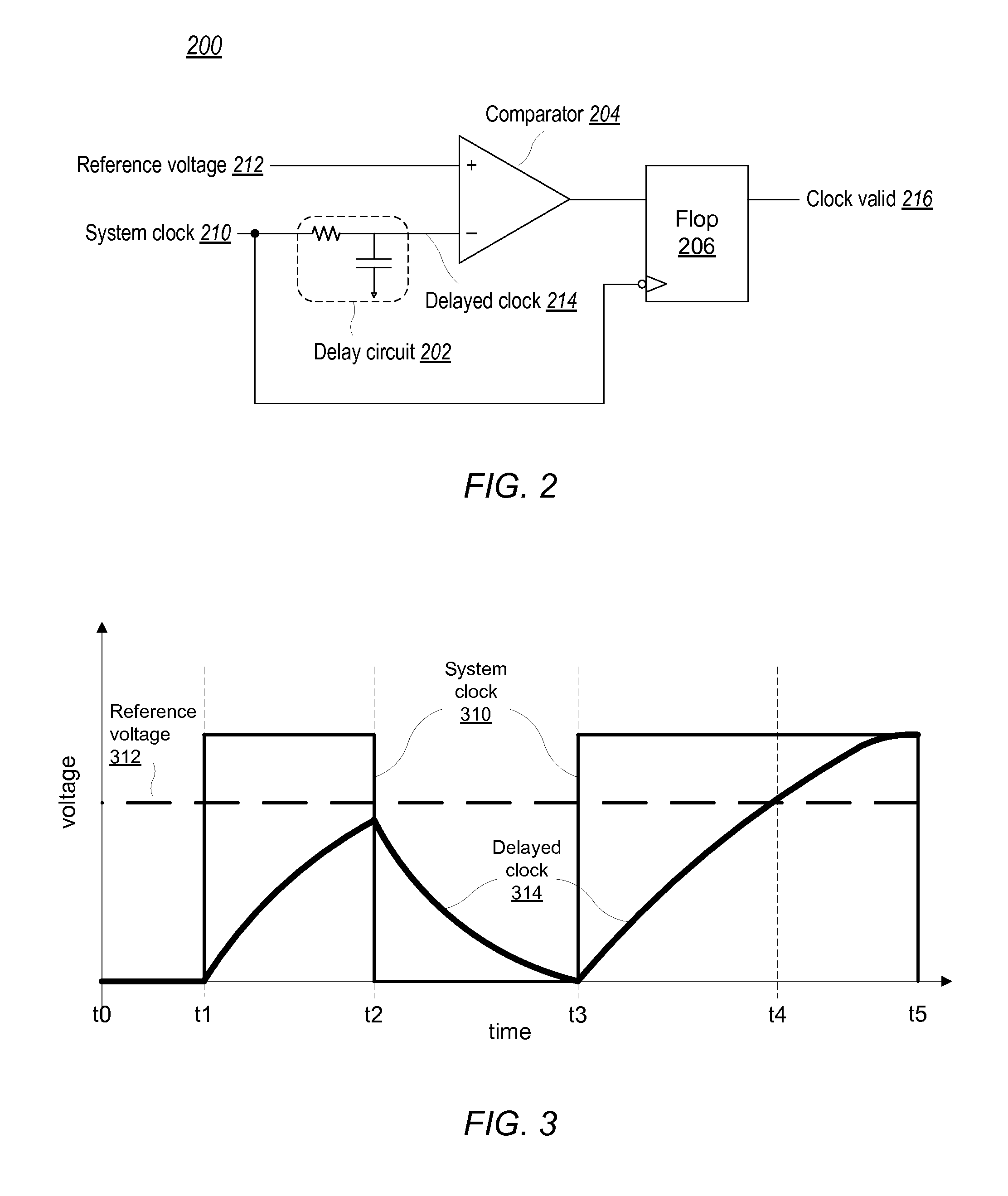
[0012]FIG. 2 illustrates a block diagram of a clock monitoring circuit.

[0013]FIG. 3 shows a first timing diagram illustrating possible signals of an embodiment of the clock monitoring circuit of FIG. 2.

second embodiment

[0014]FIG. 4 illustrates a block diagram of a clock monitoring circuit.

[0015]FIG. 5 illustrates a second timing diagram showing possible signals of an embodiment of the clock monitoring circuit of FIG. 4.

[0016]FIG. 6 shows an embodiment of a block diagram of a clock monitoring system.

[0017]FIG. 7 show a timing diagram illustrating possible signals of an embodiment of the clock monitoring system of FIG. 6.

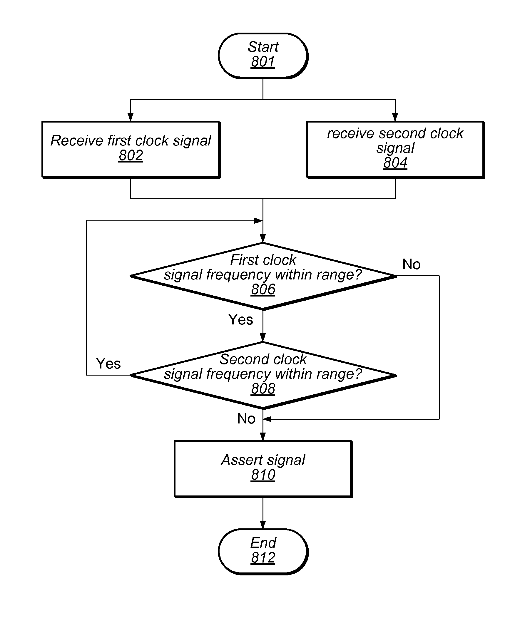
[0018]FIG. 8 depicts a flowchart illustrating an embodiment of a method for monitoring a frequency of two clock signals.

[0019]FIG. 9 illustrates a second embodiment of a block diagram of a clock monitoring system.

[0020]While the disclosure is susceptible to various modifications and alternative forms, specific embodiments thereof are shown by way of example in the drawings and will herein be described in detail. It should be understood, however, that the drawings and detailed description thereto are not intended to limit the disclosure to the particular form illustrated, but on the ...


PUM


Abstract

An apparatus may include first and second clock monitors. The first clock monitor may be configured to receive a first clock signal and assert a first signal if the frequency of the first clock signal is greater than a first upper threshold and assert a second signal if the frequency of the first clock signal is less than a first lower threshold. The second clock monitor may be configured to receive a second clock signal with a frequency higher than that of the first clock signal. The second clock monitor may be configured to compare the second clock signal, dependent upon the first clock signal, to second upper and lower thresholds and assert a third signal if the frequency of the second clock signal is greater than the second upper threshold and assert a fourth signal if the frequency is less than the second lower threshold.

Description

BACKGROUND[0001]Technical Field[0002]Embodiments described herein are related to the field of integrated circuit implementation, and more particularly to the implementation of clock signal frequency monitors.[0003]Description of the Related Art[0004]Computing systems may include one or more systems-on-a-chip (SoCs), which may integrate a number of different functions, such as, application execution, graphics processing and audio processing, onto a single integrated circuit. With numerous functions included in a single integrated circuit, chip count may be kept low in mobile computing systems, such as tablets, for example, which may result in reduced assembly costs, and a smaller form factor for such mobile computing systems.[0005]SoC designs may include one or more clock signal generators, configured to output a clock signal at a target frequency. Proper operation of some SoC designs may require clock signals with frequencies within a given range of the target frequency. If a clock ...

Claims


Application Information

Patent Timeline
IPC IPC(8): H03K5/19H03K5/26
CPCH03K5/26H03K5/19
Inventor YU, SHU-YIALLEGRUCCI, JEAN-DIDIERPAASKE, TIMOTHYBALKAN, DENIZ
Owner APPLE INC
Features
  • R&D
  • Intellectual Property
  • Life Sciences
  • Materials
  • Tech Scout
  • Unparalleled Data Quality
  • Higher Quality Content
  • 60% Fewer Hallucinations
Learn More