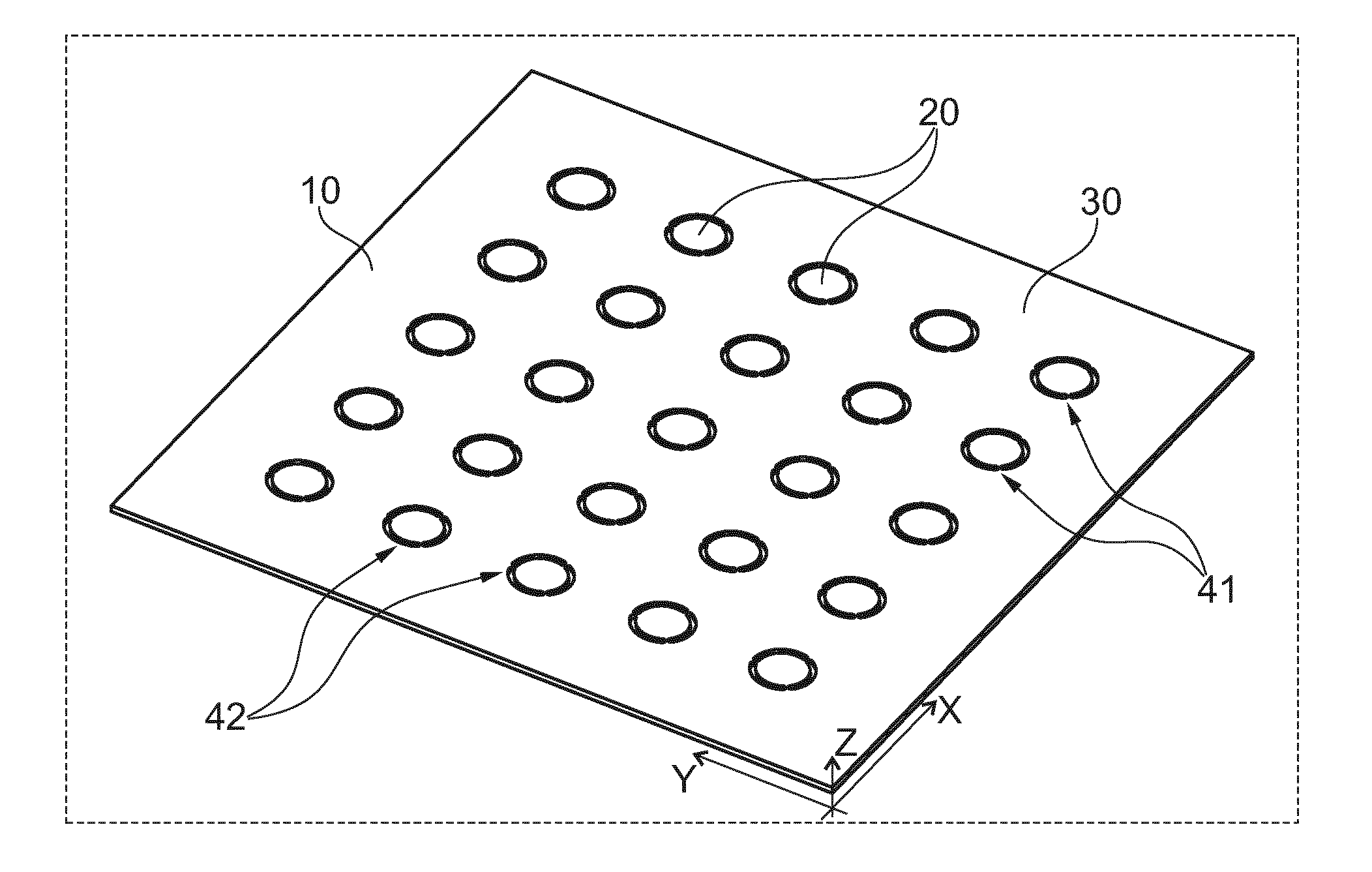
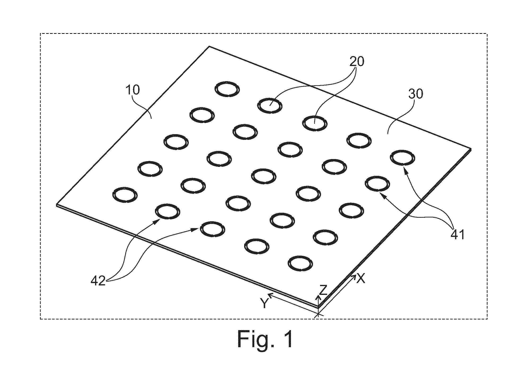
Integrated polymer foil, patch-clamp array and membrane valves
a technology of patch-clamp array and polymer foil, which is applied in the direction of measuring devices, instruments, laboratory apparatus, etc., can solve the problems of difficult to obtain polymeric materials with a sufficiently high surface smoothness for establishing giga-seals, time-consuming and expensive manufacturing techniques, and difficult to manufacture chips
- Summary
- Abstract
- Description
- Claims
- Application Information
AI Technical Summary
Benefits of technology
Problems solved by technology
Method used
Image

Examples
example 1
[0078]Commercially available foils (20-100 um) are have segments cut out then patch holes are drilled. Laser parameters are selected for the best performance of speed and quality. In the laser welding unit, the carrier substrate with four alignment holes is placed on the laser welding fixture with matching alignment pins. The foil is blown off with compressed air to remove debris then is placed on top of the carrier substrate / laser welding fixture. A quartz glass compression plate is used to ensure maximum contact between foil and substrate. Laser welding is then performed. The welded part is removed from the fixture with specified areas of welded foil, in this case, within the cut-out circumference completely, and covering the first third of the cut-out tabs (release portions). At this point, quality control, (visual, liquid or other) is done. If other surface coatings are done (glass, PTFE type coatings, low drug adsorption coatings for drug discovery), then the foil proceeds to t...
PUM
 Abstract
Description
Claims
Application Information