Valve device and hydraulic control system

Active Publication Date: 2016-12-15
DENSO CORP
View PDF3 Cites 10 Cited by
  • Summary
  • Abstract
  • Description
  • Claims
  • Application Information

AI Technical Summary

Benefits of technology

[0029]Accordingly, it is possible in the present disclosure to provide the rotary type valve device, the dimensions of which can be made smaller in its axial direction and its radial direction. In other words, it is possi

Problems solved by technology

Accordingly, it becomes more and more difficult that the valve device having the above complex structure is smoothly mounted in the engine room.
However, such a valve device is not sufficiently reduced in the size and the weight.
(1) In the rotary type valve device, the valve member of the cylindrical shape is rotated so as to increase or decrease the opening area of the fluid port. When the valve member is simply made longer in its axial direction and the multiple valve portions are arranged in the axial direction so as to provide the multi-stage valve structure, an outer shape of the valve device inevitably becomes larger. In addition, it is correspondingly necessary to provide a larger actuator in order to rotate the valve member of the rotary type, the outer shape of which has become larger.
(2) In the rotary type valve device, it is necessary to carry out a desired multi-stage opening-closing control during the valve member of the cylindrical shape is rotated by one rotation (360°). Therefore, an effective rotational angle is restricted in each of the valve portions formed in each of the multiple stages, depending on a number of the multiple stages. It becomes necessary to form a larger fluid port in each of the valv

Method used


Image

  • Valve device and hydraulic control system
  • Valve device and hydraulic control system
  • Valve device and hydraulic control system

Examples


Embodiment Construction

[0039]The present disclosure will be explained hereinafter by way of an embodiment with reference to the drawings. However, the present disclosure is not limited to the embodiment.

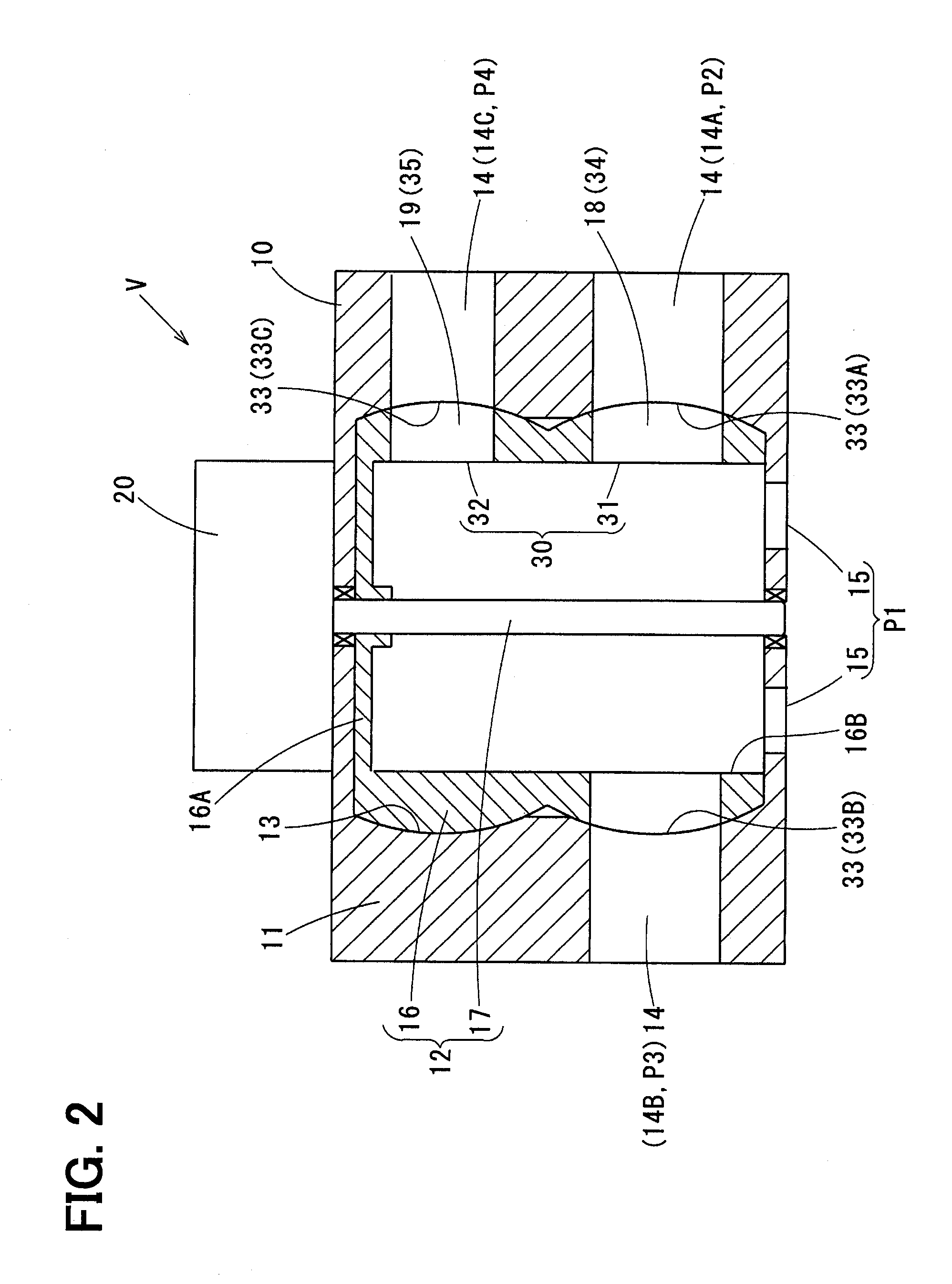
[0040]A valve device V and a hydraulic control system 100 of the embodiment of the present disclosure are applied to, for example, a cooling system 100 for an internal combustion engine E (hereinafter, the engine) of a vehicle.

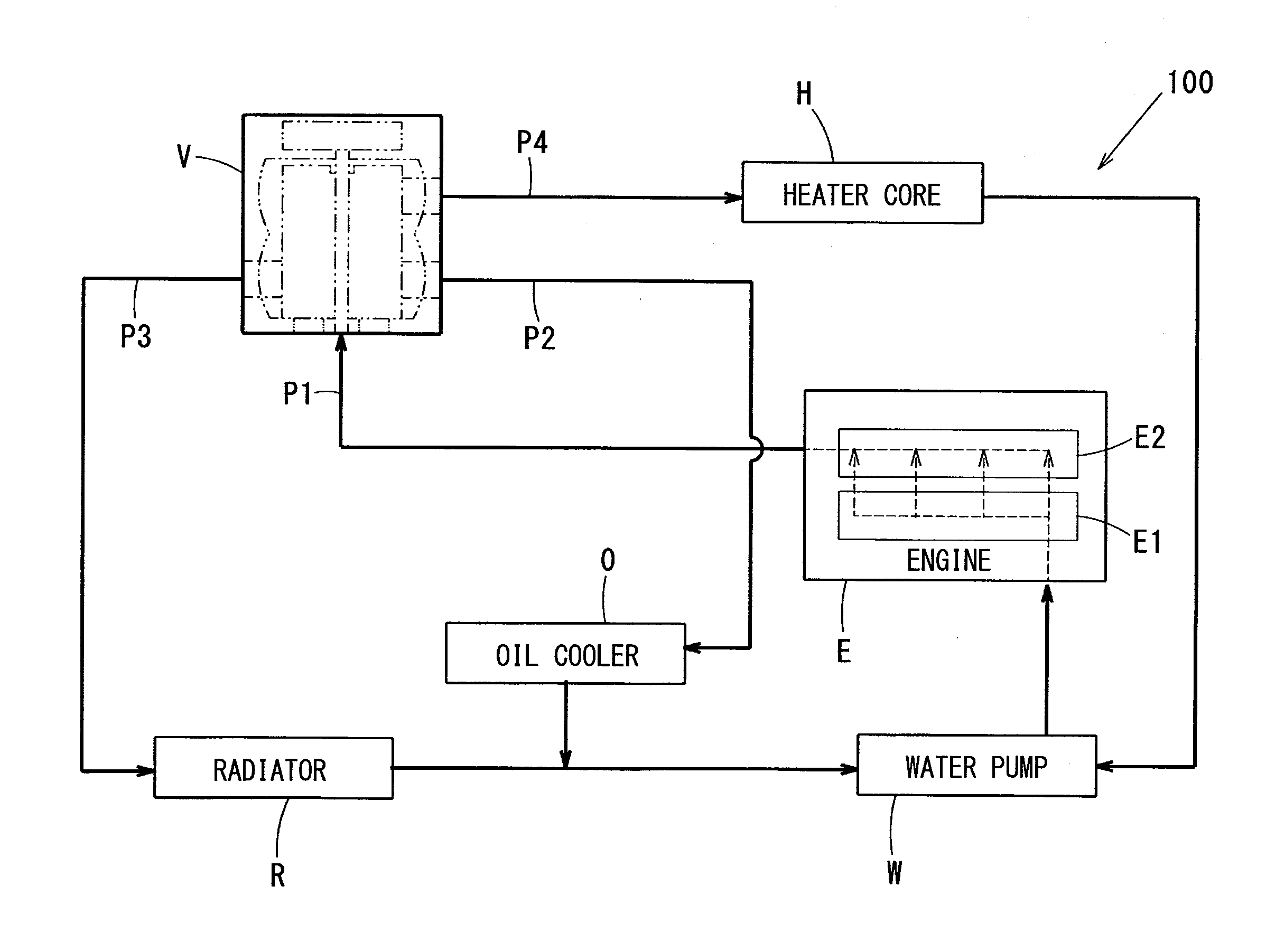
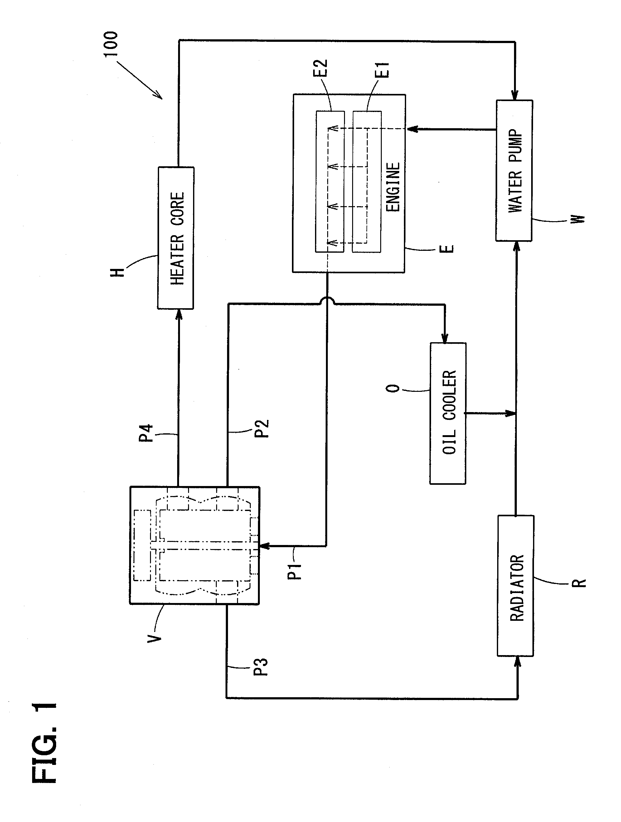
[0041]An entire structure of the cooling system 100 for the engine E will be explained with reference to FIG. 1.

[0042]In the cooling system 100 for the engine E, a controlled object is engine cooling water (hereinafter, the cooling water) for cooling the engine E. Components included in the cooling system 100 are a water pump W, an oil cooler O, a radiator R and a heater core H. Those components are connected to one another via multiple fluid passages P1 to P4. The valve device V is provided in order to open and / or close those fluid passages P1 to P4.

[0043]The water pump W, which is ...


PUM


Abstract

A first valve portion and a second valve portion are formed in a rotary valve, wherein the first and the second valve portions are arranged in an axial direction thereof. The first valve portion includes a first and a second valve windows formed in a valve member, and a first and a second valve port openings formed in a valve housing. The second valve portion includes a third valve window formed in the valve member and a third valve port opening formed in the valve housing. The valve member is rotatable in both directions of a clockwise direction and an anti-clockwise direction, so that each of the first to the third valve port openings is respectively opened or closed by the first to third valve windows. Each of the valve windows and the valve port openings of the first valve portion is formed in a rectangular shape in its developed figure in a rotational direction of the valve member.

Description

CROSS REFERENCE TO RELATED APPLICATION[0001]This application is based on Japanese Patent Application No. 2015-118536 filed on Jun. 11, 2015, the disclosure of which is incorporated herein by reference.FIELD OF TECHNOLOGY[0002]The present disclosure relates to a valve device arranged in a fluid passage for opening and closing the fluid passage, and in particular, relates to a valve device which is composed of a rotary type valve for opening and closing multiple fluid passages and a hydraulic control system having the valve device.BACKGROUND[0003]A valve device, which is composed of a rotary type valve, is known in the art and practically used, for example, as disclosed in Japanese Patent Publication No. 2002-327851.[0004]A rotary type valve having the following structure is generally used in the valve device. The rotary type valve is composed of a valve housing having multiple fluid ports and a cylindrical valve member movably accommodated in the valve housing for respectively openin...

Claims


Application Information

Patent Timeline
IPC IPC(8): F01P7/16
CPCF01P2007/146F01P7/16F01P7/14F16K31/041Y10T137/86863F16K11/0856
Inventor IMASAKA, YUSUKE
Owner DENSO CORP
Why Eureka
Try Eureka