
Broadcast signal receiving apparatus and multi-layer printed circuit board

Inactive Publication Date: 2016-12-15
SAMSUNG ELECTRONICS CO LTD
View PDF3 Cites 14 Cited by
  • Summary
  • Abstract
  • Description
  • Claims
  • Application Information

AI Technical Summary

Benefits of technology

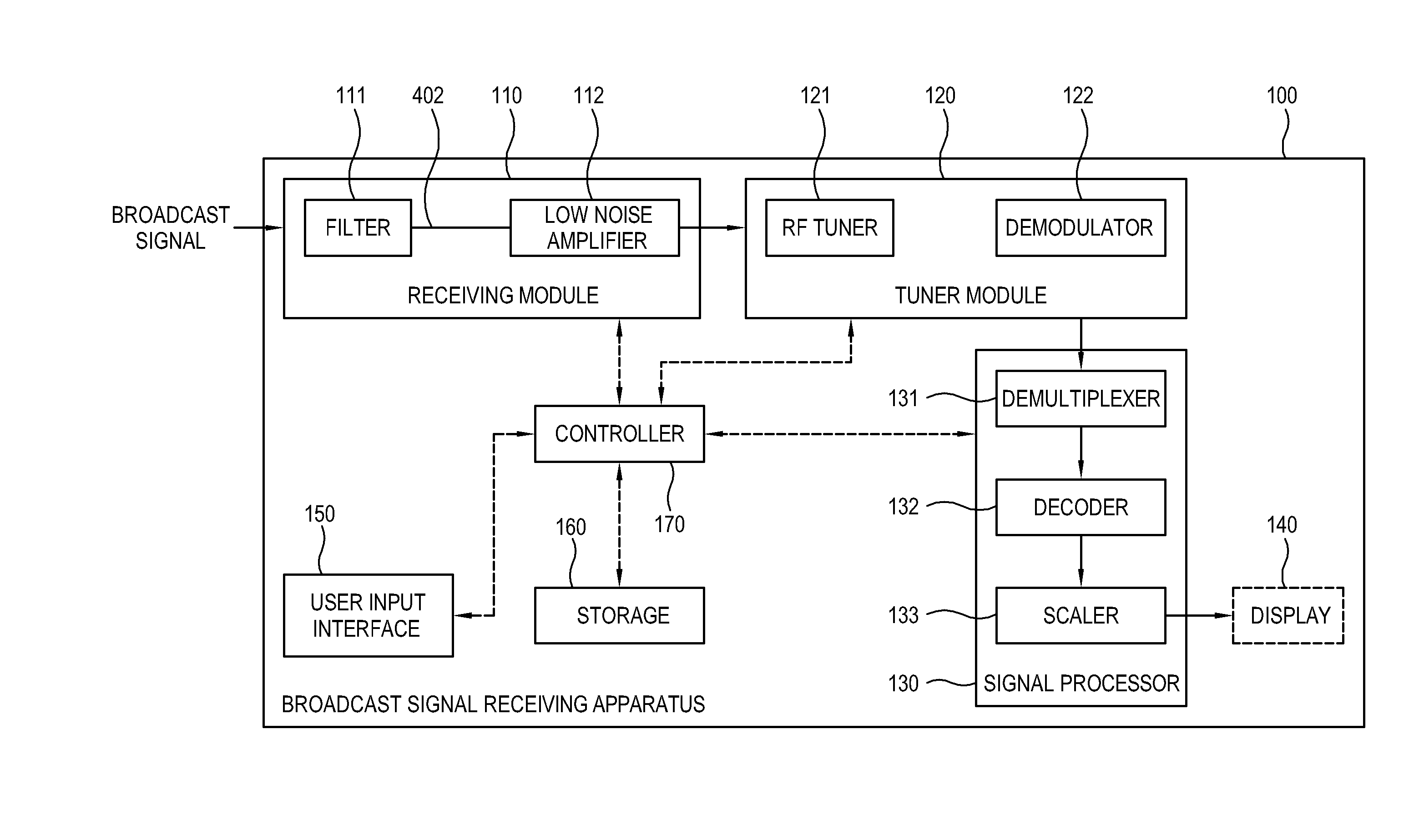
The invention is a broadcast signal receiving apparatus that includes a multi-layer printed circuit board with components for processing broadcast signals. The apparatus has a signal line for receiving the broadcast signal which may be on an inner layer of the circuit board. This allows for an input entrance for the broadcast signal without increasing material costs. The impedance of the inner layer where the signal line is provided has a predetermined reference value to reduce distortion of the broadcast signal due to interference with external signals having a frequency band overlapping with that of the broadcast signal. This prevents the broadcast signal from being distorted. The reference value is determined to meet regulations at a predetermined frequency band to ensure a product that satisfies the requirements of the broadcast operator.

Problems solved by technology

In such a band where the frequencies overlap each other, there may be interference between signals.
If the frequency of the broadcast signal overlaps with an external interference frequency, the reception sensitivity of the broadcast signal becomes poor and thus image / sound qualities are deteriorated.
In addition, the poor reception sensitivity may cause problems of suddenly stopping an image or making reception be not available.

Method used


Image

  • Broadcast signal receiving apparatus and multi-layer printed circuit board
  • Broadcast signal receiving apparatus and multi-layer printed circuit board
  • Broadcast signal receiving apparatus and multi-layer printed circuit board

Examples


Embodiment Construction

[0059]Below, exemplary embodiments will be described with reference to accompanying drawings to such an extent as to be easily realized by a person having an ordinary knowledge in the art. The present inventive concept is not limited to the exemplary embodiments set forth herein, and may be materialized variously. For clarity, elements not directly related to the elements of the exemplary embodiment may be omitted, and like numerals refer to like elements throughout. In the following descriptions, terms such as “include” or “have” refer to presence of features, numbers, steps, operations, elements or combination thereof, and do not exclude presence or addition of one or more other features, numbers, steps, operations, elements or combination thereof.

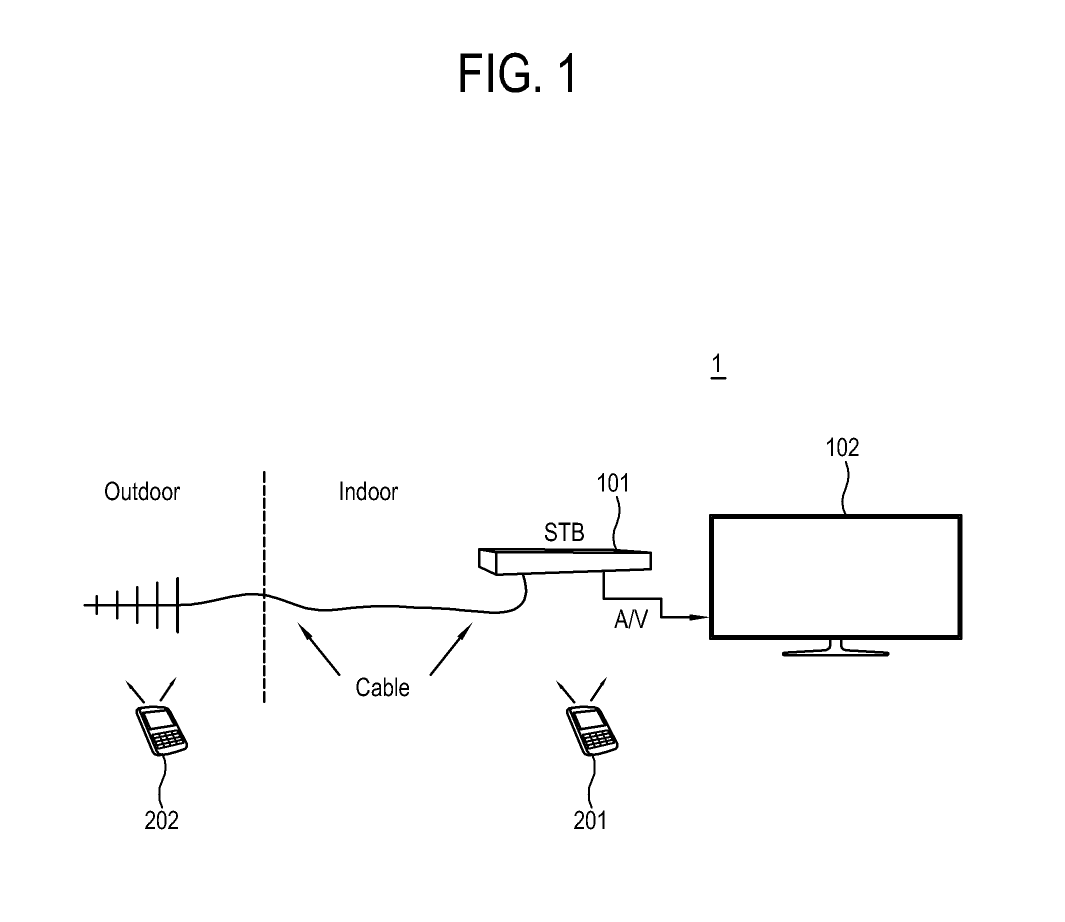
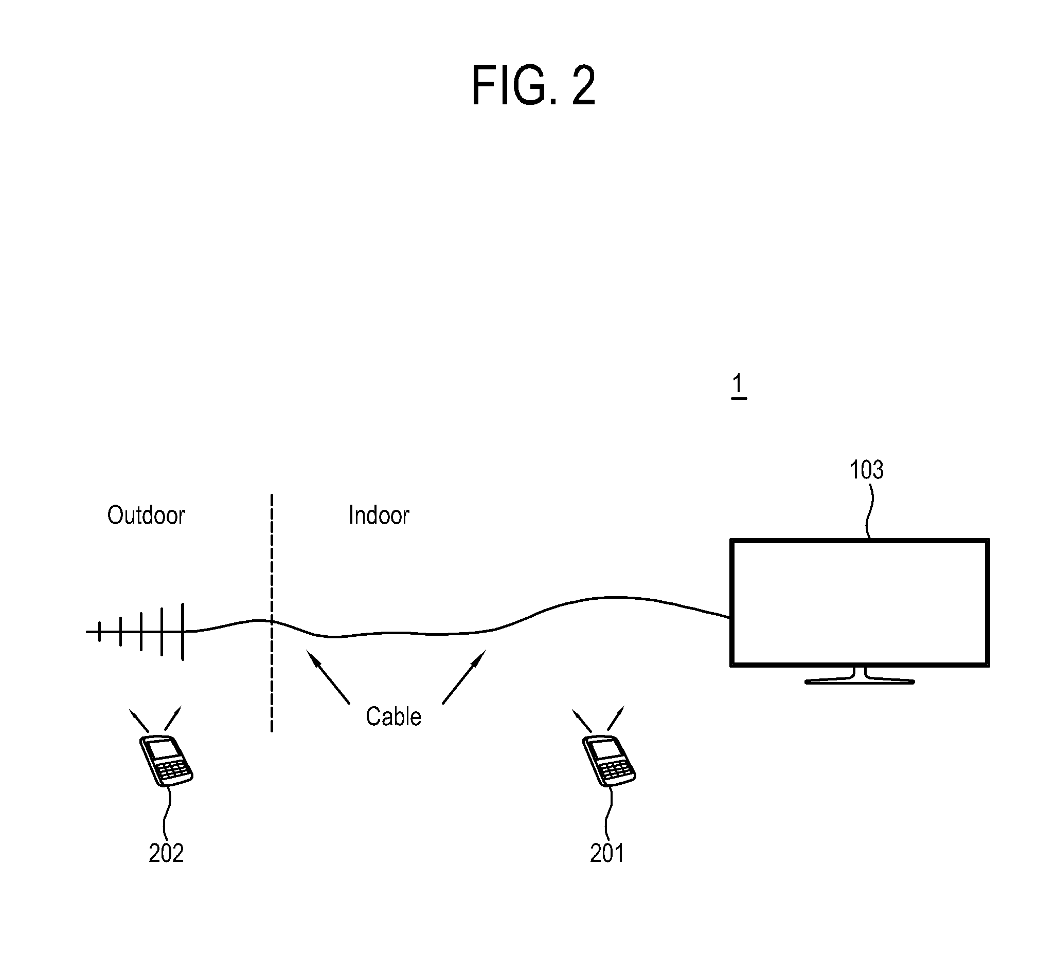
[0060]FIG. 1 and FIG. 2 schematically illustrate a broadcast signal receiving system 1 according to an exemplary embodiment;

[0061]As shown in FIG. 1 and FIG. 2, the broadcast signal receiving system 1 according to an exemplary embodiment...


PUM


Abstract

A broadcast signal receiving apparatus, including a multi-layer printed circuit board comprising a transmission line configured to connect with at least one component mounted on the multi-layer printed circuit board, the at least one component being configured to process a broadcast signal received from an outside of the apparatus through a cable, wherein a signal line for receiving the broadcast signal is at least partially provided on an inner layer of the multi-layer printed circuit board.

Description

CROSS-REFERENCE TO RELATED APPLICATION[0001]This application claims priority from Korean Patent Application No. 10-2015-0082024, filed on Jun. 10, 2015 in the Korean Intellectual Property Office, the disclosure of which is incorporated herein by reference in its entirety.BACKGROUND[0002]Field[0003]Apparatuses and methods consistent with the exemplary embodiments relate to a broadcast signal receiving apparatus and a multi-layer printed circuit board included in the same, and more particularly to a broadcast signal receiving apparatus for receiving a broadcast signal from the exterior and a multi-layer printed circuit board included in the same.[0004]Description of Related Art[0005]A broadcast signal receiving apparatus receives satellite, cable and terrestrial broadcast signals and process them to be displayed as images. The broadcast signal receiving apparatus may display the processed broadcast signal as an image on its own display panel or may output the processed broadcast signa...

Claims


Application Information

Patent Timeline
IPC IPC(8): H04B1/10H04B1/16
CPCH04B1/16H04B1/109
Inventor KIM, HYUN-JUNLEE, SUNG-SOOHONG, HWAN-SUNLEE, JA-HUNLEE, CHEOL-HEE
Owner SAMSUNG ELECTRONICS CO LTD
Learn More