

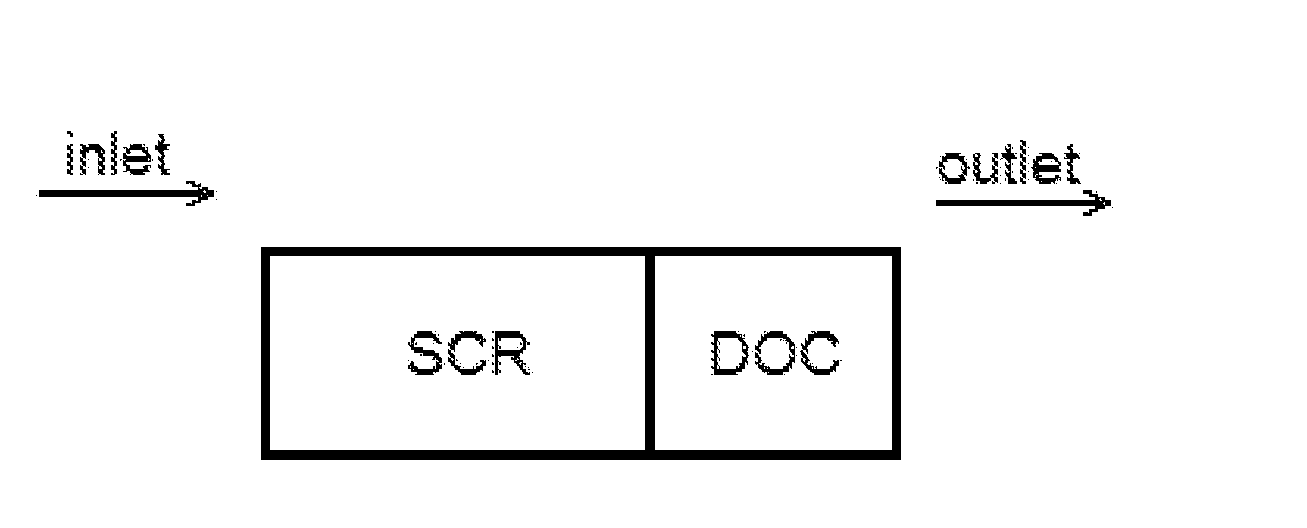
Zoned Exhaust System
a technology of exhaust system and zoned exhaust, which is applied in the direction of physical/chemical process catalysts, metal/metal-oxide/metal-hydroxide catalysts, separation processes, etc., can solve the problems of releasing excess ammonia into the atmosphere, the environment, and affecting the health of peopl
- Summary
- Abstract
- Description
- Claims
- Application Information
AI Technical Summary
Benefits of technology
Problems solved by technology
Method used
Image

Examples
example 1
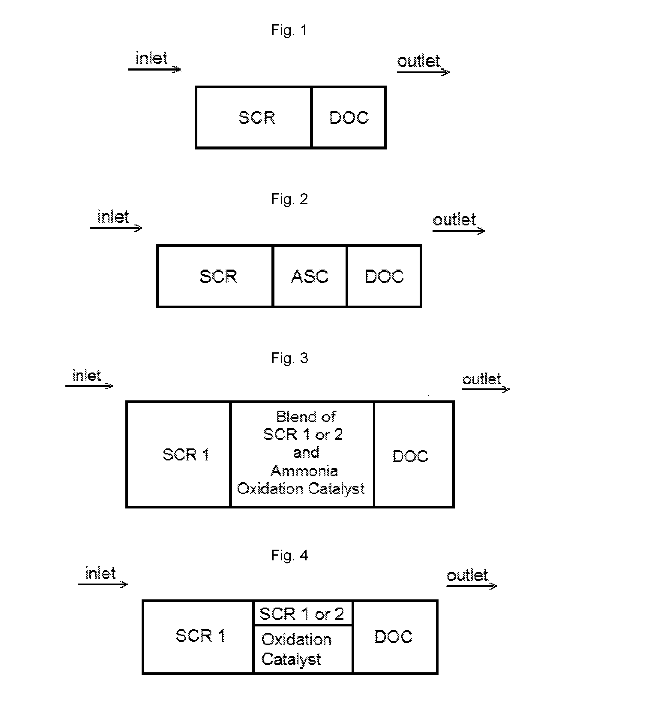
[0130]A catalytic article is prepared by first forming a layer comprising an ammonia oxidation catalyst by placing a washcoat containing one of the ammonia oxidation catalysts below on an extruded honeycomb substrate from the outlet end towards the inlet end, where the washcoat covers 50% of the length of the substrate. The amount of the ammonia oxidation catalyst is as described below.
ExampleAmmonia oxidation catalysta12% SiO2 - TiO2 - 0.94 g / in3, Boehmite alumina - 0.06 g / in3bPt-nitrate - 3 g / ft3cFER zeolite - 0.5 g / in3, Pt-nitrate - 3 g / ft3dFe-BEA zeolite - 0.5 g / in3
The layer is then dried at an elevated temperature.
[0131]A layer comprising a DOC is then placed over a portion of the layer comprising the ammonia oxidation catalyst by placing a washcoat containing one of the DOCs below over layer comprising the ammonia oxidation from the outlet end towards the inlet end.
ExampleDOC catalystePt - 3 g / ft3fPt & Pd - 3 g / ft3 and 10 g / ft3
The layer is then dried at an elevated temperature...
example 2
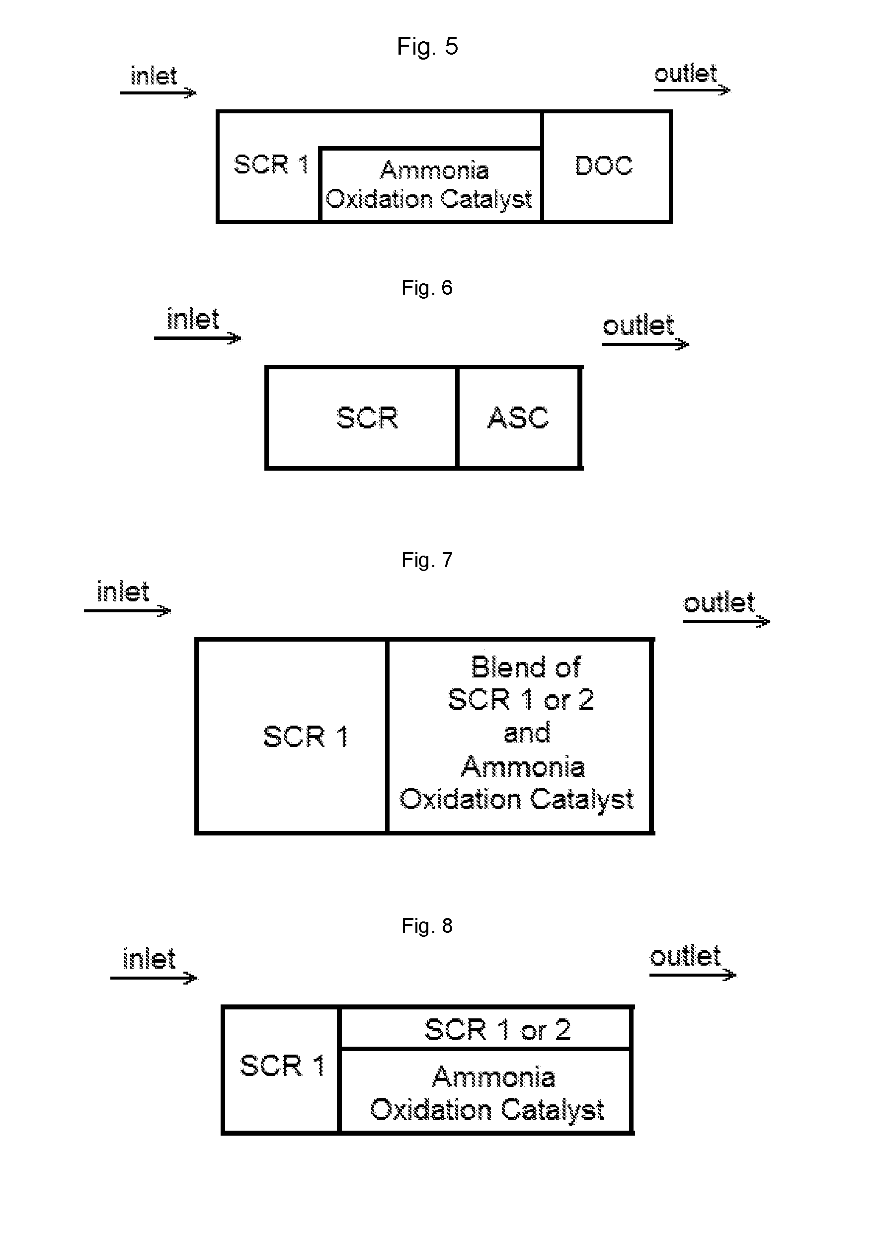
[0134]A catalytic article is prepared by forming a first layer comprising a mixture of an ammonia oxidation catalyst and a DOC by placing a washcoat containing one of the ammonia oxidation catalysts shown in Example 1 with a DOC described in Example 1 on an extruded honeycomb substrate from the outlet end towards the inlet end, where the washcoat covers 50% of the length of the substrate. The layer is then dried at an elevated temperature. A second layer comprising the mixture of the ammonia oxidation catalyst and the DOC is then formed by the washcoat comprising the mixture of the ammonia oxidation catalyst and the DOC over a portion, but not all, of the first layer. The results in the formation of the mixture of an ammonia oxidation catalyst and a DOC into a two-step structure, where the second step, located closest to the outlet, is thicker than the first step. The layer is then dried at an elevated temperature.
[0135]A layer comprising an SCR catalyst is then placed over the rema...
example 3
[0137]A catalytic article is prepared by forming a first layer comprising an ammonia oxidation catalyst by placing a washcoat containing one of the ammonia oxidation catalysts shown in Example 1 on an extruded honeycomb substrate from the outlet end towards the inlet end, where the washcoat covers 50% of the length of the substrate. The layer is then dried at an elevated temperature. A second layer comprising the DOC is then formed by placing a washcoat comprising the DOC over a portion, but not all, of the first layer. The layer is then dried at an elevated temperature.
[0138]A layer comprising a first SCR catalyst is then placed over the remaining uncoated portion of the substrate and the uncoated portion of the layer comprising the ammonia oxidation catalyst by placing a washcoat containing 3.3 wt. % Cu / CHA at a loading of 2.07 g / in3 on the substrate from the inlet end towards the outlet end. The washcoat is placed over the layer comprising the ammonia oxidation catalyst such that...
PUM
| Property | Measurement | Unit |
|---|---|---|
| temperatures | aaaaa | aaaaa |
| temperatures | aaaaa | aaaaa |
| temperatures | aaaaa | aaaaa |
Abstract
Description
Claims
Application Information