Image forming apparatus and method

Active Publication Date: 2016-12-22
CANON KK
View PDF3 Cites 10 Cited by
  • Summary
  • Abstract
  • Description
  • Claims
  • Application Information

AI Technical Summary

Benefits of technology

[0010]The present invention has been made in light of the above issue, and even in an image forming apparatus that performs scanning in the main scanning

Problems solved by technology

Such a scanning lens having the fθ characteristic is relatively large and expensive.
However, if a conventional counting method is used in an image forming apparatus that performs scanning in a main scanning direction at a scanning speed that is not constant, there is a pos

Method used


Image

  • Image forming apparatus and method
  • Image forming apparatus and method
  • Image forming apparatus and method

Examples


first embodiment

[0029]Configuration of Image Forming Apparatus

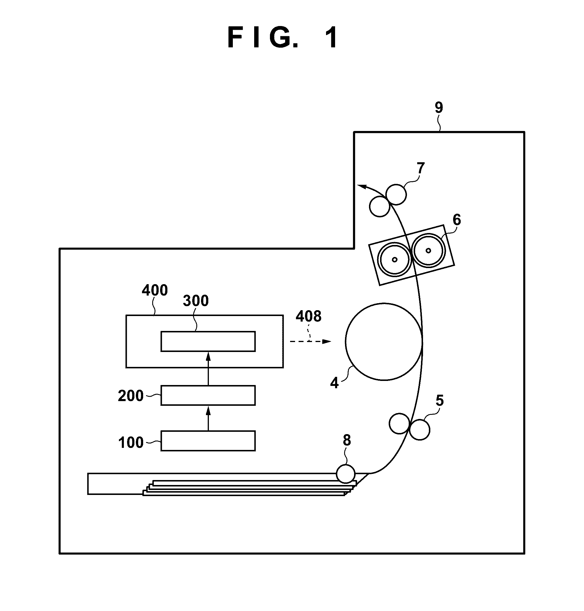
[0030]FIG. 1 is a schematic diagram showing the configuration of an image forming apparatus 9. A laser driving unit 300 within a light scanning unit 400, which is a light scanner, turns on scanning light (laser light) 208 based on image signals output from an image signal generation unit 100, and control signals output from a control unit 200. A photosensitive member (photosensitive drum) 4 charged by a charger (not illustrated) is operated with the laser light 208 so as to form a latent image on the surface of the photosensitive drum 4. The scanning light 208 is modulated so as to be turned on / off based on image signals that have undergone pulse width modulation, for example. Toner is attached to the latent image formed on the photosensitive drum 4 by a developing means (not illustrated) for storing toner as a developing agent, thereby forming a toner image. The toner image is transferred to a recording medium such as paper, which is fe...

second embodiment

[0069]In this embodiment, a configuration will be described in which a result similar to the first embodiment is obtained by weighting the calculation of an accumulation result of pixel counting. The difference is that the pixel count unit 202 of the first embodiment is changed to a pixel count unit 702. The configuration of this embodiment will be described below. The same reference numerals are assigned to the constituent elements similar to those in the first embodiment and the description thereof is omitted.

[0070]FIG. 7 is an electrical block diagram of image formation of this image forming apparatus 9 in this embodiment. This example is the same as the first embodiment in that the pixel count unit 702 receives the partial magnification characteristics information from the CPU 201 via the CPU bus 211 and obtains various setting values, and only processing executed by the pixel count unit 702 is different. Note that this embodiment is different from the first embodiment in that t...

third embodiment

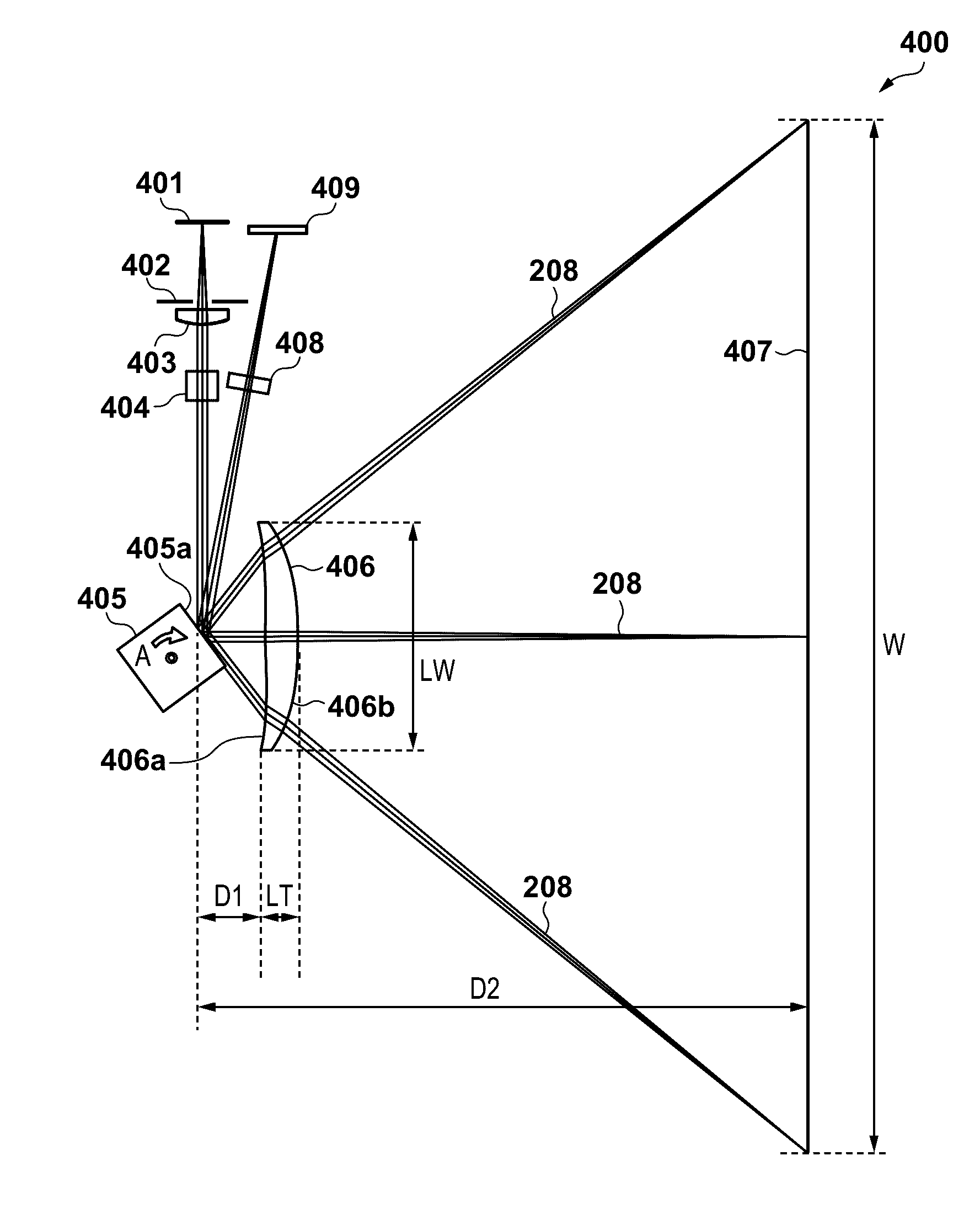
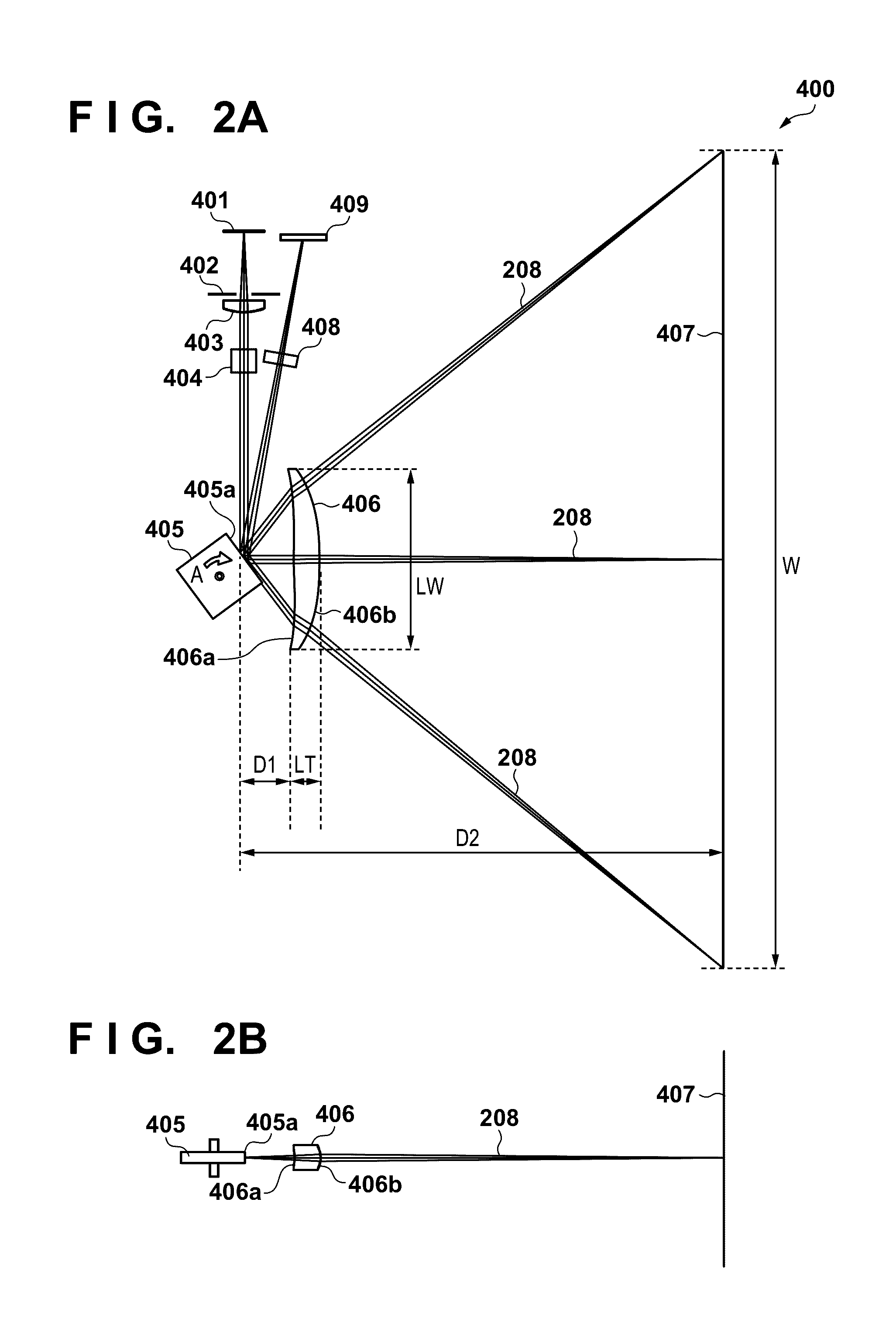
[0077]In this embodiment, a configuration will be described in which pixel counting is performed for each of a plurality of areas obtained by dividing the image area in the main scanning direction, and after calculating the laser lighting ratio of each of the areas, the laser lighting ratio is multiplied by a predetermined correction coefficient and the calculation results for the areas are then averaged. A luminous flux converged by a lens that does not have the fθ characteristic such as the image forming lens 406 of this embodiment has different spot diameters at the on-axis image height and an off-axis image height, to be precise. Usually, the image forming apparatus 9 is designed such that change in the spot diameter in one main scanning operation does not influence the image quality, but in this embodiment, in order to more accurately estimate the toner consumption amount, a laser lighting ratio calculation value is corrected by multiplying the weighting coefficient calculated ...


PUM


Abstract

There is provided an image forming apparatus comprising: a scanning unit configured to scan, in accordance with image signals, a photosensitive member with laser light in a main scanning direction at a scanning speed that is not constant; an image signal generation unit configured to generate image signals that are changed such that the faster the scanning speed is, the narrower an image signal width becomes; a clock signal generation unit configured to generate sampling clock signals for sampling the image signals whose image signal width is changed such that the faster the scanning speed is, the shorter a sampling interval becomes; and a count unit configured to count image signals whose image signal width is changed based on the sampling clock signals.

Description

BACKGROUND OF THE INVENTION[0001]Field of the Invention[0002]The present invention relates to prediction of the remaining amount of a consumable material in an image forming apparatus such as an electrophotographic printer.[0003]Description of the Related Art[0004]Electrophotographic image forming apparatuses have an optical scanning unit for exposing a photosensitive member. The optical scanning unit emits laser light based on image data, reflects the laser light with a rotating polygon mirror, and causes the laser light to pass through a scanning lens, so as to irradiate and expose the photosensitive member. Scanning is performed in which a laser light spot formed on the surface of the photosensitive member is moved by rotating the rotating polygon mirror, whereby a latent image is formed on the photosensitive member.[0005]The scanning lens is a lens having so-called an fθ (f-theta) characteristic. The fθ characteristic is an optical characteristic according to which the laser lig...

Claims


Application Information

Patent Timeline
IPC IPC(8): B41J2/385
CPCG03G15/043G03G15/0898G03G21/14
Inventor NAKAJIMA, YUKIARAKI, GOKANAZAWA, HIDENORI
Owner CANON KK
Why Eureka
Try Eureka