Fuel Cell Stack Arrangement

Active Publication Date: 2016-12-29
CERES INTPROP CO LTD
View PDF3 Cites 10 Cited by
  • Summary
  • Abstract
  • Description
  • Claims
  • Application Information

AI Technical Summary

Benefits of technology

[0154]During start-up, the electrochemically inactive fuel cell stack repeat layers separate the mode dynamic heating capacity of the metal supported cells from the larger thermal mass of the end plate, thus allowing for a faster start-up. Thus, providing the electrochemically inactive layers between the electrochemically active layers and the base plate/end plate acts to thermally decouple them, i.e. the large thermal mass of the baseplate and endplate and their corresponding higher thermal inertia is decoupled from the low thermal mass fuel cells and electrochemically active repeat layers. This is particularly the case where an additional heat source is provided in the form of heat from a pre-heater. Thus, not only is heat loss reduced from the electrochemically active repeat layers adjacent or proximal the at least one electrochemically inactive fuel repeat layer, but a heated inlet flow of oxidant or fuel can additionally effect heating of the at least one electrochemically inactive repeat layer and thus effect heating of electrochemically active repeat layers which are adjacent or proximal.
[0155]Reducing the time lag effect of the base plate and end plate thermal masses allows the electrochemically active cell

Problems solved by technology

Significant challenges in mechanical, electrical and thermal design are encountered when designing SOFC (solid oxide fuel cell) stacks, particularly IT-SOFC (intermediate temperature solid oxide fuel cell) stacks, which are required to operate in an efficient manner which caters for start-up, dynamic operation, and shut-down.
One feature of all SOFC stacks is that their operating performance is affected by the temperature that they operate at, and hence they can be significantly affected by the environmental temperature they operate in.
This “end effect” can result in a drop in fuel cell electrochemical operating performance (in particular, a voltage drop) of the fuel cells at the ends of the stack when compared to those not at the ends of the stack.
This in turn reduces the overall efficiency of the stack.
The variation in temperature between fuel cells in different parts of the fuel cell stack (e.g. (a) at the top and bottom, and (b) in the middle) can also make controlling the stack temperature difficult since it results in a divergent set of temperatures of individual fuel cells within the fuel cell stack.
Thus, optimising temperature to achieve the best overall efficiency can be difficult.
As well as temperature differences between individ

Method used


Image

  • Fuel Cell Stack Arrangement
  • Fuel Cell Stack Arrangement
  • Fuel Cell Stack Arrangement

Examples


Example

EXAMPLE 1

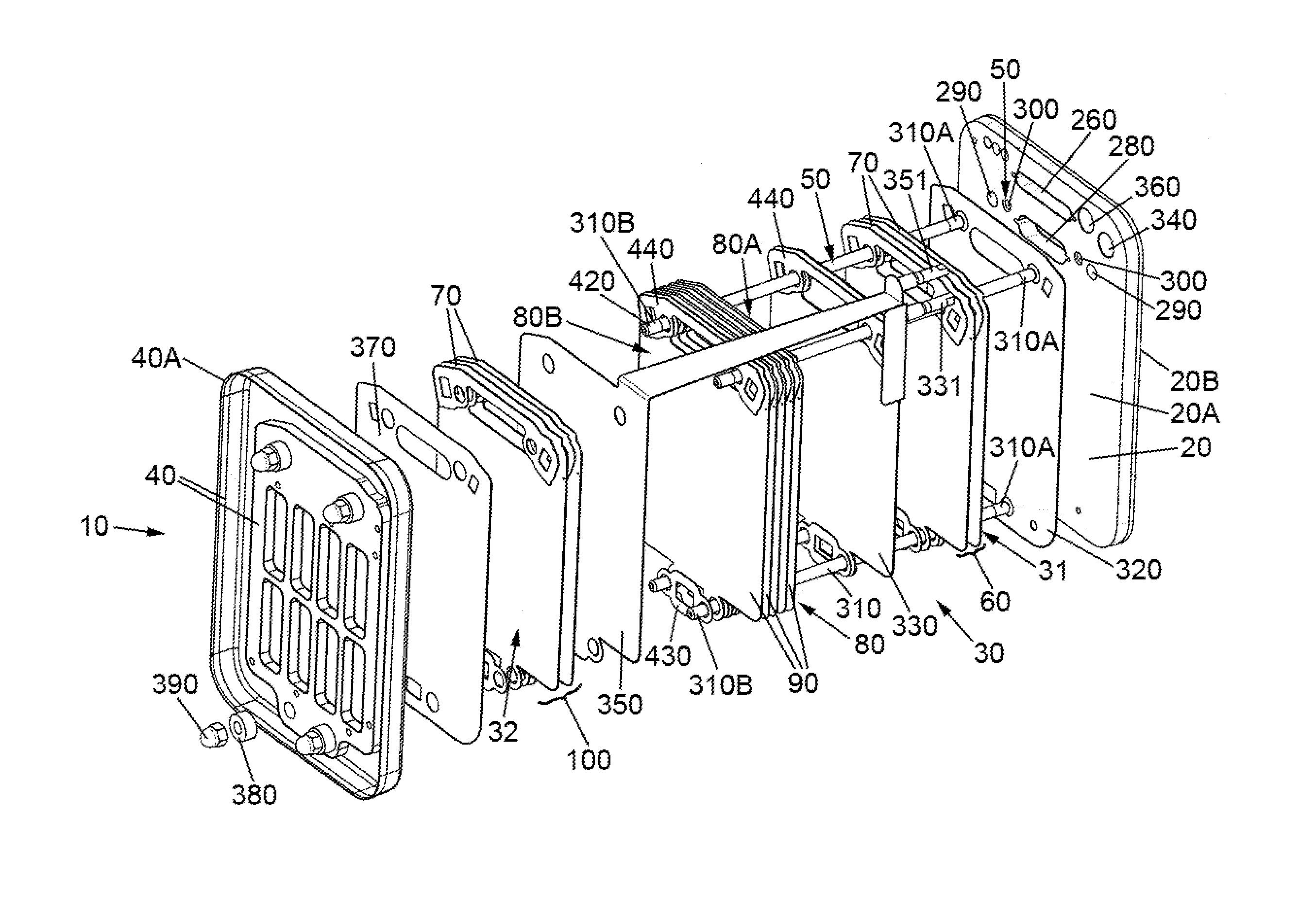
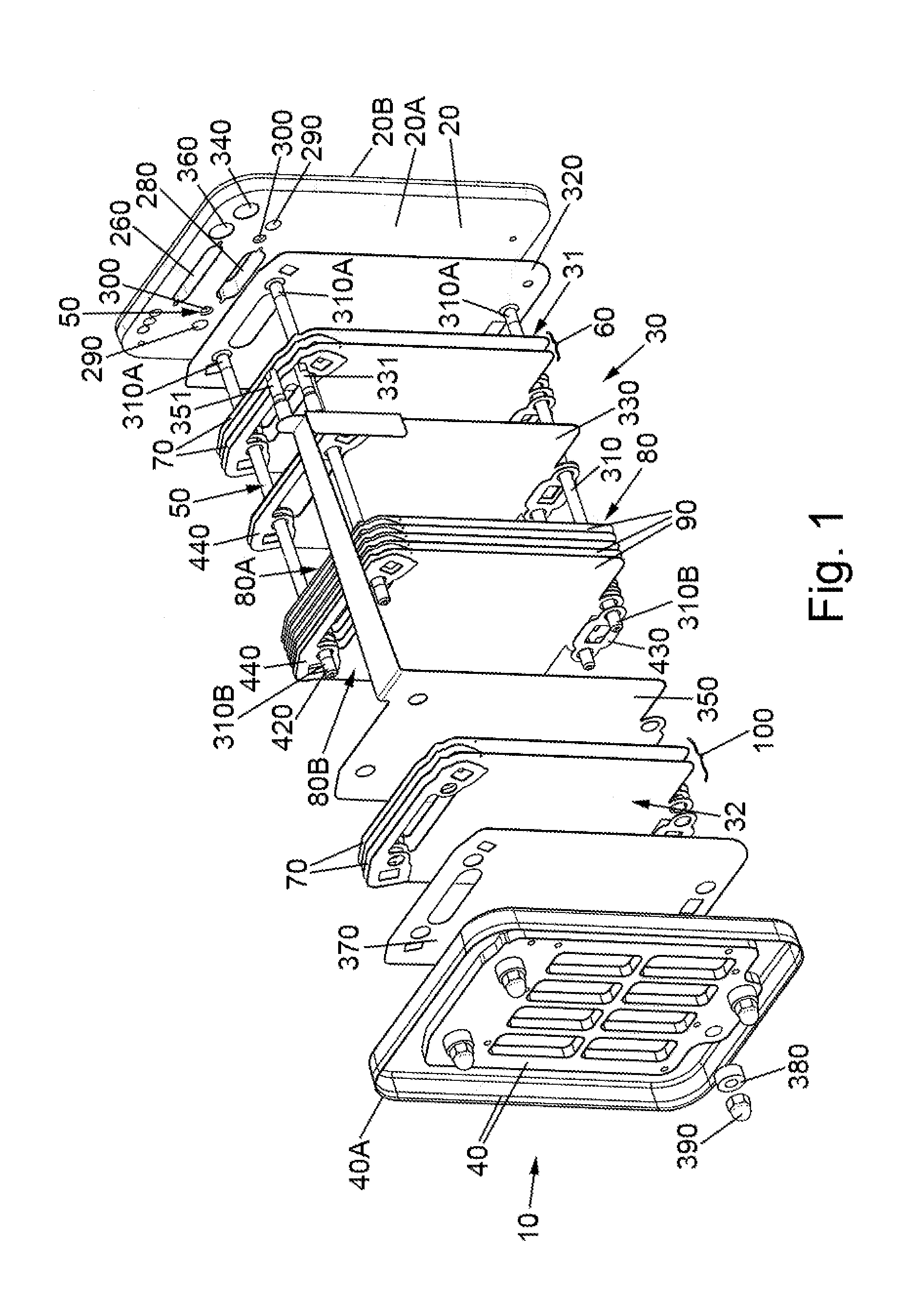
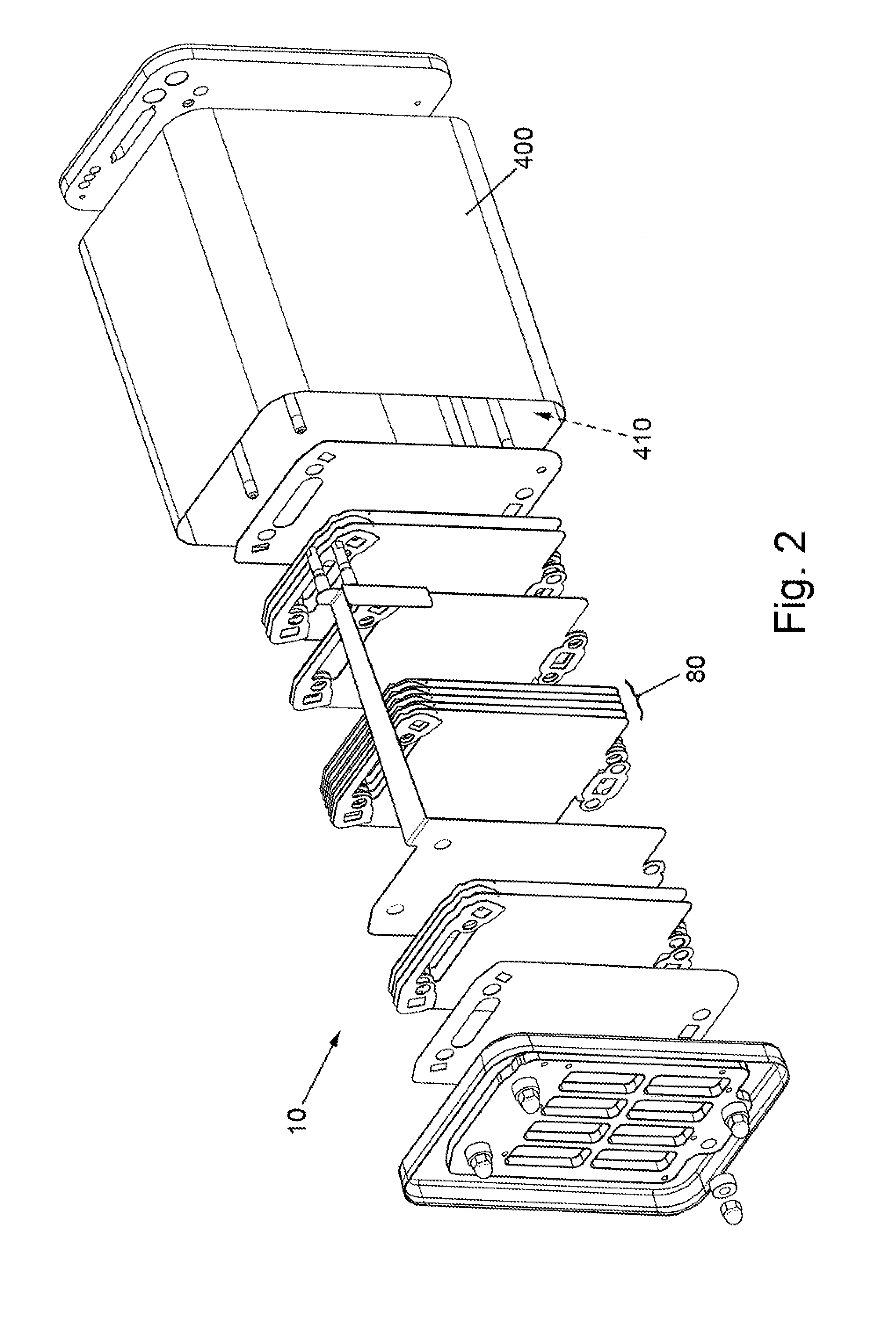
[0262]In order to determine the effect of the incorporation of electrochemically inactive fuel cell stack repeat layers in a fuel cell stack assembly, comparative data was obtained from first and second intermediate-temperature solid oxide fuel cell stack assemblies.

[0263]The first intermediate-temperature solid oxide fuel cell stack assembly (referred to as being “With buffer inactive layers”) is a fuel cell stack assembly as per Embodiment 1 (above).

[0264]The second intermediate-temperature solid oxide fuel cell stack assembly (referred to as being “Without buffer inactive layers”) is identical to the first intermediate-temperature solid oxide fuel cell stack assembly except that it does not include any electrochemically inactive fuel cell stack repeat layers, i.e. does not include a first set of electrochemically inactive fuel cell stack repeat layers, and does not include a second set of electrochemically inactive fuel cell stack repeat layers.

[0265]In the experiments, ...


PUM


Abstract

The present invention is concerned with improved fuel cell stack assembly arrangements.

Description

FIELD OF THE INVENTION[0001]The present invention is concerned with improved fuel cell stack assembly arrangements.BACKGROUND OF THE INVENTION[0002]Teachings of fuel cells, fuel cell stacks, fuel cell stack assemblies, and heat exchanger systems, arrangements and methods are well known to one of ordinary skill in the art, and in particular include WO02 / 35628, WO03 / 07582, WO2004 / 089848, WO2005 / 078843, WO2006 / 079800, WO 2006 / 106334, WO 2007 / 085863, WO 2007 / 110587, WO 2008 / 001119, WO 2008 / 003976, WO2008 / 015461, WO2008 / 053213, WO2008 / 104760, WO2008 / 132493, WO2009 / 090419, WO2010 / 020797, WO2010 / 061190, and WO2015 / 004419. All publications referenced herein and their references are incorporated herein by reference in their entirety. Definitions of terms used herein can be found as necessary in the above publications. In particular, the present invention seeks to improve the systems and methods disclosed in WO 2007 / 085863 and WO2008 / 104760.[0003]Fuel Cell Temperature Variation, Start-Up and ...

Claims


Application Information

Patent Timeline
IPC IPC(8): H01M8/247H01M8/0206H01M8/12H01M8/2425
CPCH01M8/247H01M8/2425H01M2008/1293H01M8/12H01M8/0206H01M8/04082H01M8/2432Y02P70/50Y02E60/50H01M8/02H01M8/04H01M8/24H01M8/2465
Inventor LEAH, ROBERTBONE, ADAMREES, LEE
Owner CERES INTPROP CO LTD
Why Eureka
Try Eureka