Dual-band phased array antenna with built-in grating lobe mitigation

Active Publication Date: 2016-12-29
HENSOLDT SENSORS GMBH
View PDF6 Cites 14 Cited by
  • Summary
  • Abstract
  • Description
  • Claims
  • Application Information

AI Technical Summary

Benefits of technology

[0025]Using this design of the invention saves approximately 90% of radiating elements with connected TRMs compared to known arrays with an antenna segmentation for the different scanning areas at the upper bands as these are used in AESA. This is a huge cost reduction due to reduced number of radiating elements required. Additionally, only one type of radiating element is required compared to arrays with special partitioning using different kind of radiating elements. Even system design is easier and less complex as compared to prior art antennas. As the resolution is improved, the array can be designed either smaller or with a better resolution using the same array size. Manufacturing is less complex as no partiti

Problems solved by technology

In order to achieve small antenna beams a large number of TRMs is required, which may be expensive.
Antennas with high gain require a relatively high number of radiating elements, which may become expensive taking into account that for each radiating element an associated TRM is needed.
Increasing the size of the radiating elements will result in larger antenna aperture, smaller antenna beams, higher antenna directivity, and better angular resolution but with the drawback of grating lobes, especially at large scanning angles.
Lowering the operation frequency would reduce or avoid the grating lobe problems, but antenna beam width would increase, directivity and angular resol

Method used


Image

  • Dual-band phased array antenna with built-in grating lobe mitigation
  • Dual-band phased array antenna with built-in grating lobe mitigation
  • Dual-band phased array antenna with built-in grating lobe mitigation

Examples


Embodiment Construction

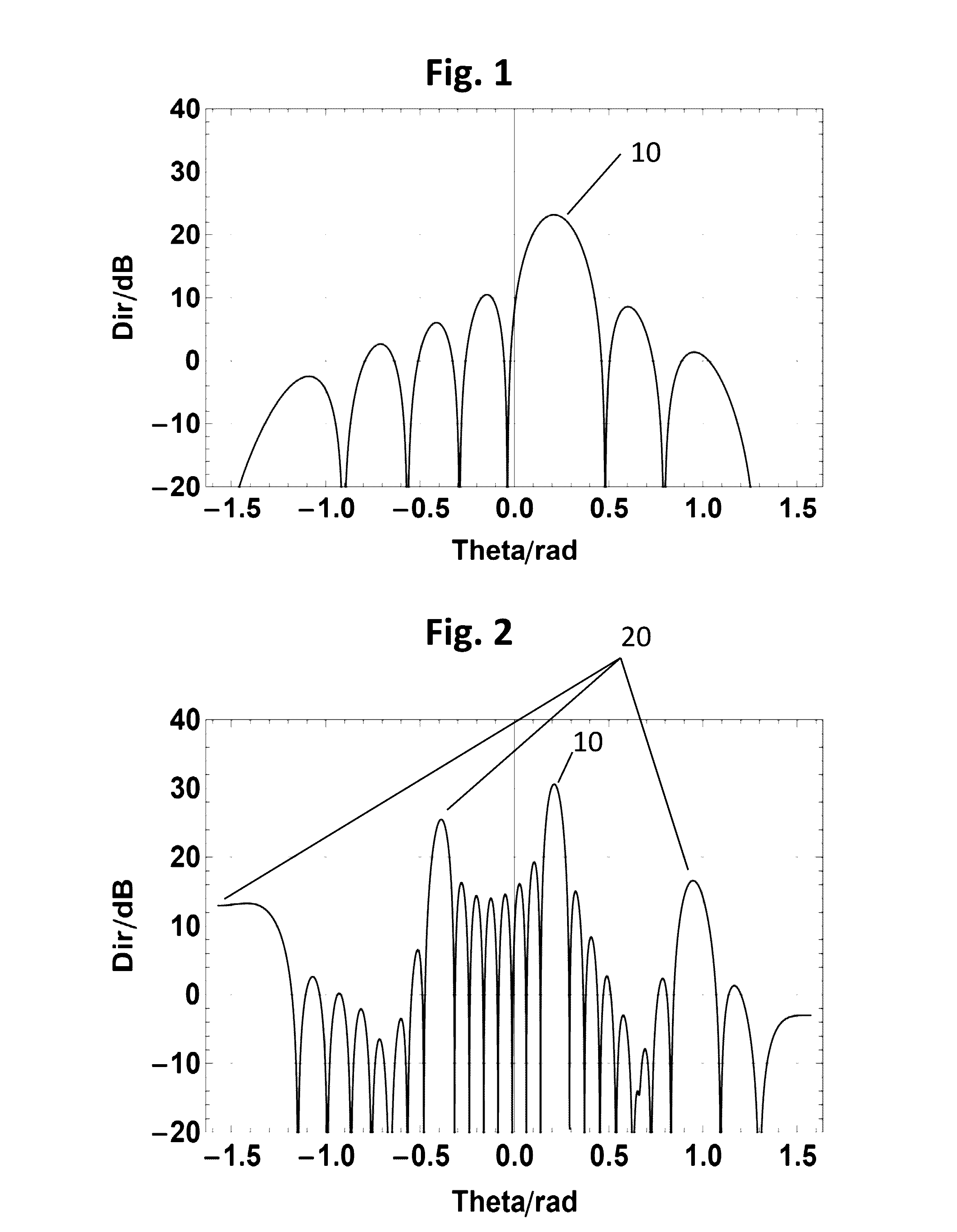
[0036]It is well known in phased array theory that the antenna pattern for sufficiently large arrays can be assumed to be the product of the element pattern and the array factor as in equation Eq 1, shown for a linear array, but not limited to linear arrays:

E(θ)=ERE(θ)ElementPattern∑nAn2πdλ(sinθ-sinθ0)nArrayFactorEq1

[0037]The first term ERE(θ) in Eq 1 is called element pattern, whereas the sum is commonly known as array factor. In this second term the individual signals with amplitude An and Phase

2πdλ(sinθ-sinθ0)n

are summed. d designates the distance between neighboring radiating elements. The phase depends on the position n*d within the array, the wavelength λ, the desired direction θ and the steering direction θ0. The array factor will have maximal amplitude when the “phase” in the exponential term becomes a multiple of 2π as noted in Eq 2:

2πdλ(sinθ-sinθ0)=k2πk∈ℤEq2

[0038]If

is smaller than 0.5, Eq 2 is solvable only for k=0 and only one major lobe exists in the whole scanning ran...


PUM


Abstract

A dual-Band phased array antenna with built-in grating lobe mitigation includes an array of radiating elements capable of working at both bands and arranged at distances small enough, avoiding grating lobes with respect to the lower band within the desired field of view. The radiating elements are arranged in planar subarrays that can be steered independently from each other and each of the subarrays has a different boresight normal vector, so that grating lobes in the upper band is mitigated.

Description

CROSS-REFERENCE TO RELATED APPLICATIONS[0001]The present application claims priority under 35 USC §119 to European Patent Application Number 15 001 899.2, filed Jun. 26, 2015, the entire content of which is herein expressly incorporated by reference.BACKGROUND OF THE INVENTION[0002]Exemplary embodiments of the invention relate to a dual-band phased array antenna with built-in grating lobe (GL) mitigation.[0003]In the field of phased array antennas it is well-known that the radiating elements (REs) must have a distance of less than half of the shortest wavelength radiated by the antenna to enable a scanning area of the antenna with a broad beam width. Associated with each radiating element is a phase shifting device or a time delaying device to enable the electronic scanning by the phased array antenna. In modern phased array antennas there are additional power amplifiers for transmission and low noise amplifiers for receiving, as well as RF switches and electronic circuits for contr...

Claims


Application Information

Patent Timeline
IPC IPC(8): H01Q21/06H01Q5/392H01Q1/36
CPCH01Q21/061H01Q5/392H01Q1/36H01Q3/26H01Q5/00H01Q21/0025H01Q21/20
Inventor GRUENER, WILHELMFELL, PETER
Owner HENSOLDT SENSORS GMBH
Why Eureka
Try Eureka