Pseudo-random chopper amplifier

a chopper-stabilized amplifier and pseudo-random technology, applied in the field of amplifiers, can solve the problems of large ripple in the passband, undermining the accuracy of measurement signals, and the stability of the chopper-stabilized architecture may have a limited bandwidth, so as to reduce the artifact of chopping

Active Publication Date: 2016-12-29
CIRTEC MEDICAL CORP
View PDF3 Cites 7 Cited by
  • Summary
  • Abstract
  • Description
  • Claims
  • Application Information

AI Technical Summary

Benefits of technology

[0008]Embodiments include an electrical circuit or device with a chopper-stabilized a

Problems solved by technology

However, a discrete time architecture can produce undesirable aliasing of noise and signals, undermining the accuracy of measurement signals.
A chopper-stabilized architecture may

Method used


Image

  • Pseudo-random chopper amplifier
  • Pseudo-random chopper amplifier
  • Pseudo-random chopper amplifier

Examples


Embodiment Construction

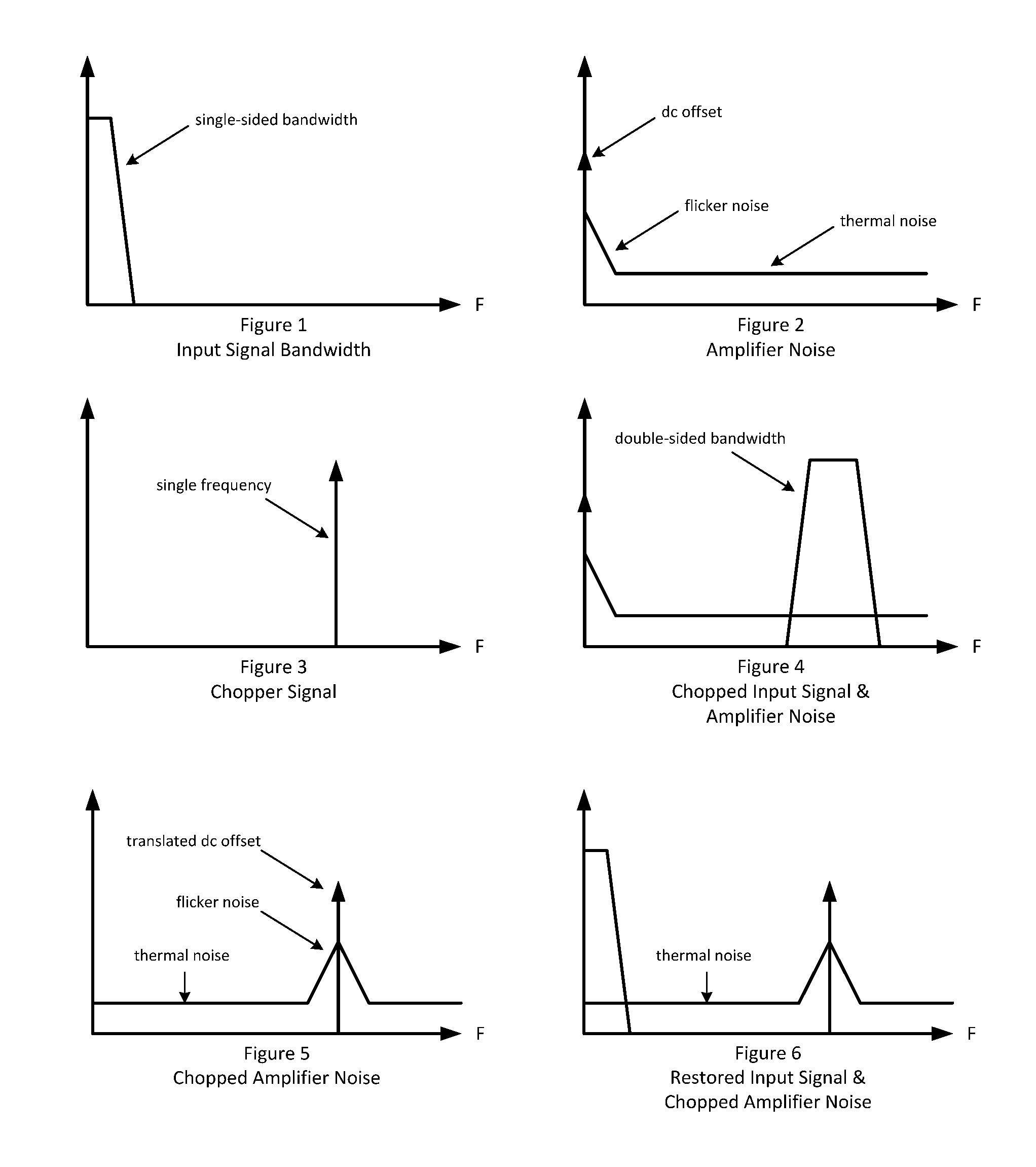
[0017]One aspect of the disclosure includes the realization that conventional amplifiers use a single “selected” frequency for the chopping signal which results in higher amplitude chopping artifacts.

[0018]Accordingly, another aspect of the disclosure includes a chopper stabilized amplifier that utilizes a multi-frequency chopping signal to reduce chopping artifacts such as low frequency 1 / f (“flicker”) noise. By utilizing a multi-frequency chopping signal, the amplifier DC offset and flicker noise are translated to the higher chopping frequencies but are also smeared, or spread out in frequency and consequently lowered in amplitude. This lower amplitude signal allows for less stringent filtering requirements.

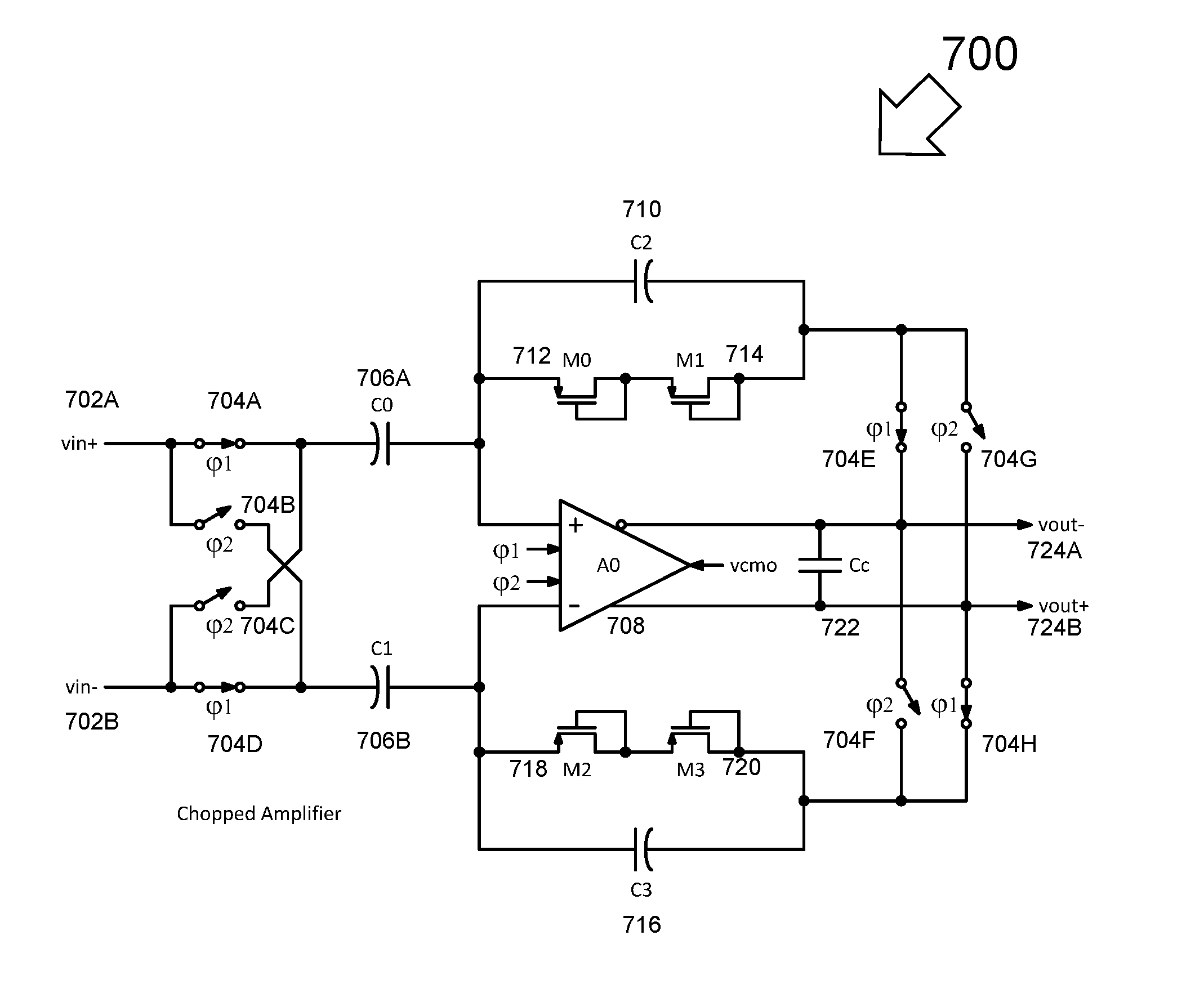
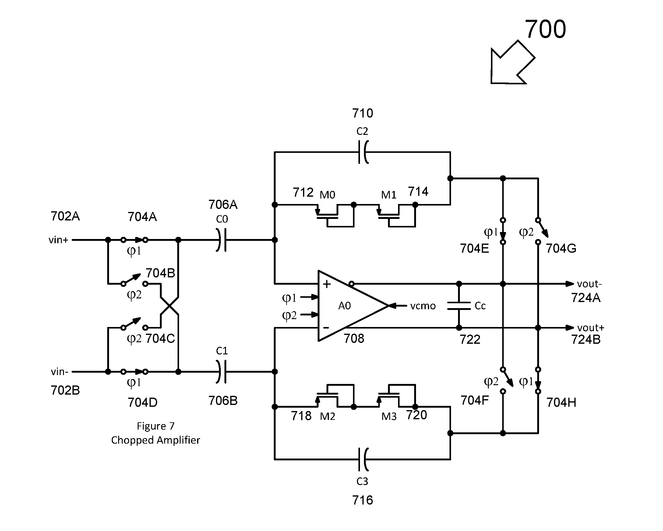
[0019]FIG. 7 is a schematic of an embodiment chopper amplifier 700, suitable for medical sensing applications, which uses a multi-frequency chopping signal, constructed and operative in accordance with an embodiment of the present disclosure. The chopper amplifier 700 may be co...


PUM


Abstract

A chopper stabilized amplifier that utilizes a multi-frequency chopping signal to reduce chopping artifacts. By utilizing a multi-frequency chopping signal, the amplifier DC offset and flicker noise are translated to the higher chopping frequencies but are also smeared, or spread out in frequency and consequently lowered in amplitude. This lower amplitude signal allows for less stringent filtering requirements.

Description

RELATED APPLICATION[0001]This non-provisional patent application claims priority to provisional U.S. Patent Application No. 62 / 185,272, entitled “Pseudo-Random Chopper Amplifier,” filed on Jun. 26, 2015 and incorporated herein by reference in its entirety.BACKGROUND[0002]Field of the Disclosure[0003]Aspects of the disclosure relate in general to amplifiers. Aspects include a chopper stabilized amplifier that utilizes a multi-frequency chopping signal to reduce chopping artifacts.[0004]Description of the Related Art[0005]Instrumentation amplifiers are used to accurately measure a variety of test and measurement signals. A medical instrumentation amplifier, for example, may be configured to measure physiological signals, such as electrocardiogram (ECG), electromyogram (EMG), electroencephalogram (EEG), pressure, impedance, and motion signals. Typically, instrumentation amplifiers are constructed as differential amplifiers exhibiting low offset, low drift, low noise, high common mode r...

Claims


Application Information

Patent Timeline
IPC IPC(8): H03F1/26H03F3/45A61B5/00A61B5/0488A61B5/0476H03F3/393A61B5/0402
CPCH03F1/26H03F3/393H03F3/45179A61B5/0402A61B5/0488H03F2200/271A61B5/7203A61B5/7228H03F2203/45288H03F2200/261A61B5/0476H03F3/45475A61B5/7225A61B5/318A61B5/369A61B5/389
Inventor MCLEOD, SCOTT CAMERON
Owner CIRTEC MEDICAL CORP
Why Eureka
Try Eureka