High-voltage direct-current thermal fuse

a high-voltage direct-current, thermal fuse technology, applied in thermally actuated switches, electric switches, electrical devices, etc., can solve the problems of insufficient elasticity of the compressing spring in the compressed state to destroy the welding strength of fusible alloy wires, and achieve the effect of preventing further damage to other components, avoiding further damage to electronic components and fir

Active Publication Date: 2017-01-05
XIAMEN SET ELECTRONICS
View PDF10 Cites 10 Cited by
  • Summary
  • Abstract
  • Description
  • Claims
  • Application Information

AI Technical Summary

Benefits of technology

[0017]The invention makes an improvement to the internal structure of the existing thermal fuse to solve the problem that the existing thermal fuse cannot be directly used in the high-voltage circuit, so that the high-voltage low-current thermal fuse can be directly used in the high-voltage direct-current circuit for protection. When the heat generated by the circuit is too high, it can cut off the circuit to avoid further damage to the electronic components and the occurrence of fire.
[0018]Furthermore, the embodiment of the invention also provides an improved solution of the high-voltage direct-current thermal fuse. By the circuit connecting manner in which the high-voltage low-current thermal fuse is connec

Problems solved by technology

The elasticity of the compressing spring in the compressed state is not suf

Method used


Image

  • High-voltage direct-current thermal fuse
  • High-voltage direct-current thermal fuse
  • High-voltage direct-current thermal fuse

Examples


embodiment 1

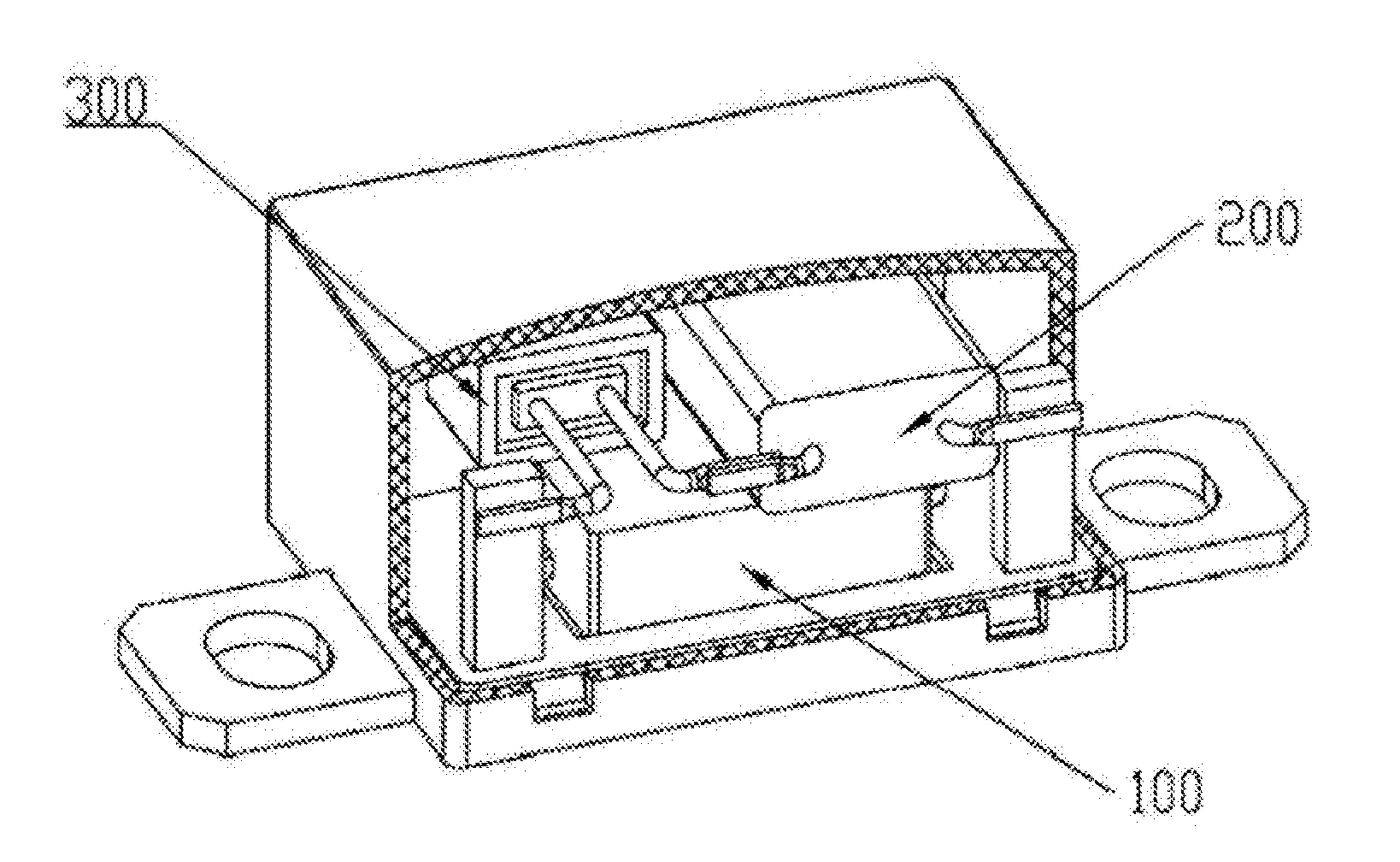
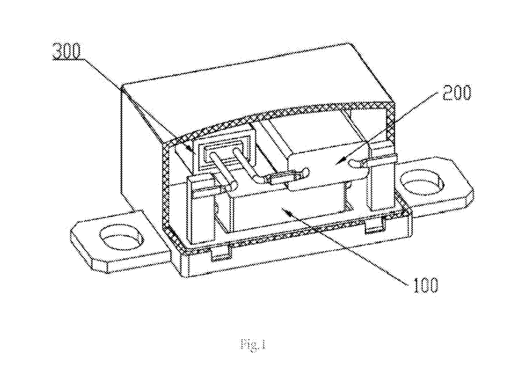
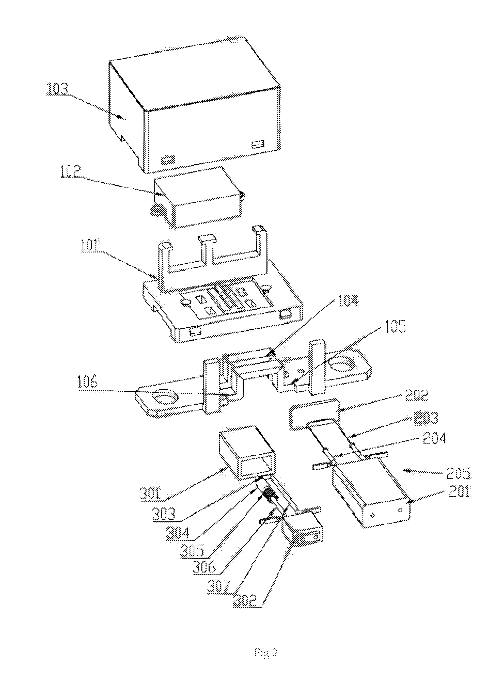
[0029]FIG. 1 and FIG. 2 respectively show the perspective partial profile diagram and the perspective explosive view of Embodiment 1 of the invention. As FIG. 1, FIG. 2 shows, the high-voltage direct-current thermal fuse of the embodiment of the invention includes insulating base 101 and a large casing 103 provided thereon. Regular thermal fuse 100, current fuse 200, and high-voltage low-current thermal fuse 300 are provided inside a cavity formed between insulating base 101 and large casing 103. Among others, high-voltage low-current thermal fuse 300 is connected in series to current fuse 200 sequentially to form a primary branch. Then, the primary branch is connected in parallel to thermal fuse 100. Next, thermal fuse 100 is connected in series into the high-voltage circuit to be protected, to provide the over-temperature protection for the high-voltage circuit.

[0030]Please refer to FIG. 2, thermal fuse 100 specifically includes small casing 102 which is arranged on insulating bas...

embodiment 2

[0041]FIG. 4 shows the circuit schematic diagram of Embodiment 2 of the invention. As an expanded solution, in this Embodiment 2, the high-voltage direct-current thermal fuse is composed of thermal fuse 100, current fuse 200, and high-voltage low-current thermal fuse 300 as the same as those in Embodiment 1. Among others, high-voltage low-current thermal fuse 300 is sequentially connected in series to current fuse 200 to form the primary branch. Next, the primary branch is connected in parallel to thermal fuse 100. Thermal fuse 100 is connected in series to the high-voltage circuit to be protected, so as to provide the over-temperature protection for the high-voltage circuit, which is not explained again here.

[0042]The differences between Embodiment 1 and Embodiment 2 lie in that: the high-voltage direct-current thermal fuse also includes N secondary branches, and each secondary branch includes the high-voltage low-current thermal fuse sequentially connected in series to the current...


PUM


Abstract

A high-voltage direct-current thermal fuse comprising a high-voltage low-current thermal fuse connected to a high-voltage direct-current circuit. The high-voltage low-current thermal fuse comprises a casing, fusible alloy wires, wherein the fusible alloy wires are connected between the two leads. One of the leads is sequentially sleeved with an arc extinguishing sleeve and a spring. One end of the arc extinguishing sleeve is in contact with the fusible alloy wires; and the other end of the arc extinguishing sleeve is in contact with the spring. One end of the spring is connected to the inner end face of the casing; and the spring is in a compressed state. The high-voltage direct-current thermal fuse further comprises a conventional thermal fuse; or further comprises a current. The high-voltage direct-current thermal fuse solves the problem of timely arc cutting-off and can be directly applied to a high-voltage direct-current circuit.

Description

TECHNICAL FIELD[0001]The invention relates to a high-voltage direct-current thermal fuse, especially relates to a high-voltage direct-current thermal fuse used for cutting off the arc in the high-voltage direct-current circuit.BACKGROUND[0002]The thermal fuse is also called thermal fusible cutout, which is usually mounted in electrical appliances which are prone to generate heat. Once the appliance fails and generates heat, and when the temperature exceeds an abnormal temperature, the thermal fuse will automatically fuse to cut off the power supply to prevent the electric appliance from being on fire. In recent years, the thermal fuse is mounted on most household appliances which have the main function of heating, such as rice cookers, electric irons, and electric furnaces. When internal parts stop working, the power supply can be cut off in time by the thermal fuse to prevent the appliance from further damage, so as to avoid causing a fire. The thermal fuse is the same as the fuse ...

Claims


Application Information

Patent Timeline
IPC IPC(8): H01H85/38
CPCH01H37/04H01H37/761H01H85/46H01H2037/762H01H85/12H01H37/76H01H85/38H01H85/30H01H85/04H01H2085/381
Inventor HONG, YAOXIANGXU, YOUSHENGXU, ZHONGHOU
Owner XIAMEN SET ELECTRONICS
Why Eureka
Try Eureka