Alumina coated cutting tool

Active Publication Date: 2017-01-12
SANDVIK INTELLECTUAL PROPERTY AB
View PDF7 Cites 14 Cited by
  • Summary
  • Abstract
  • Description
  • Claims
  • Application Information

AI Technical Summary

Benefits of technology

[0006]It was an object of the present invention to provide a coated cutting tool insert with an α-Al2O3 comprising coating showing improved surface finish, reduced surface roughness and imp

Problems solved by technology

The coating is described to exhibit good cutting performance, however, the deposition of Zr oxide in addition to Al oxide is general

Method used


Image

  • Alumina coated cutting tool
  • Alumina coated cutting tool
  • Alumina coated cutting tool

Examples


example 1

Alumina Layer According to Prior Art (Coating 1—Comparative Example)

[0103]The alumina deposition on the pre-coated substrates, as described above, was started by introducing a reaction gas mixture of 2.5 vol-% AlCl3, 4.1 vol-% CO2 and balance H2 at a temperature of 1000° C. and a pressure of 66 mbar. The reaction g as components were introduced simultaneously. After 2 min, HCl in an amount of 2.5 vol-% was added to the reaction gas mixture flowing into the reactor. After another 8 min H2S in an amount of 0.33 vol-% was added to the reaction gas mixture flowing into the reactor.

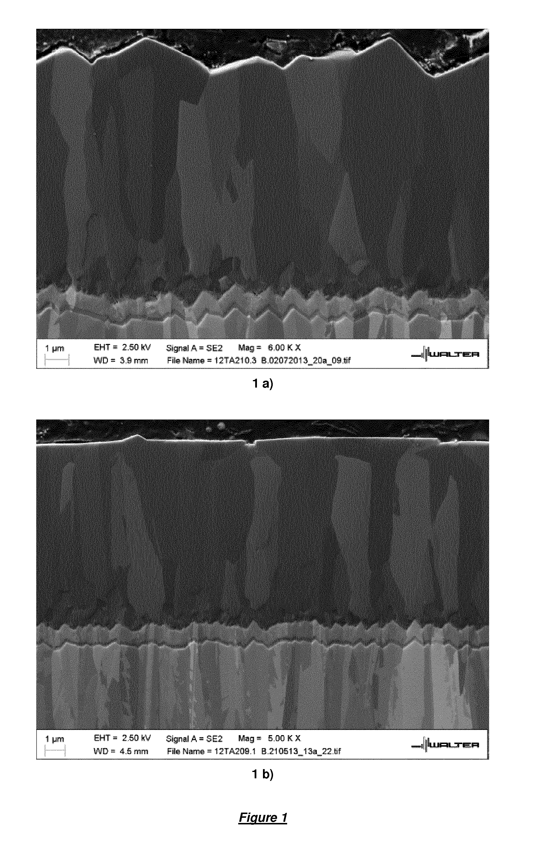
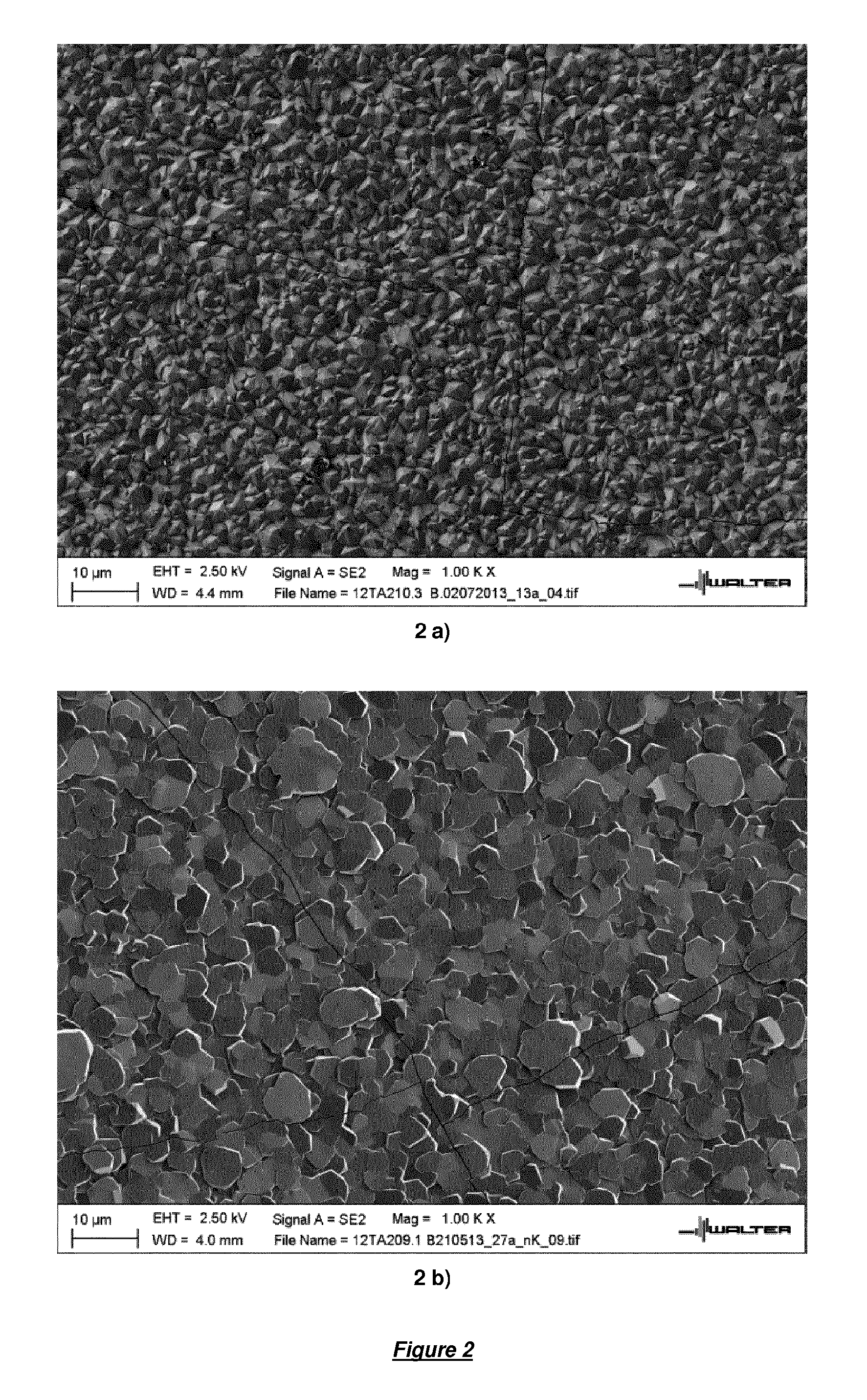
[0104]The deposition conditions were maintained for about 8 hours to obtain an about 8 μm thick α-Al2O3 layer. In a visual inspection the α-Al2O3 layer appeared dark and dull. The coating was analysed by roughness measurements, cutting tests, SEM and XRD.

example 2

Alumina Layer According to the Present Invention (Coating 2)

[0105]The alumina deposition on the pre-coated substrates was carried out as described above for example 1 with the exception that the deposition time of the α-Al2O3 layer was 6.5 hours instead of 8 hours. After 6.5 hours deposition time, the process parameters were changed to “second process conditions” that were known to favour a preferred crystal growth along the crystallographic direction of the α-Al2O3 layer. In the “second process conditions”, the composition of the reaction gas mixture was 1.5 vol-% AlCl3, 5.7 vol-% CO2, 7.5 vol-% HCl, 0.05 vol-% H2S and balance H2. The temperature was maintained at 1000° C., but the pressure was changed to 150 mbar. The deposition time under the “second process conditions” was 1.5 hours, and the total thickness of the thus obtained α-Al2O3 layer was 8 μm, as in example 1. In a visual inspection the α-Al2O3 layer appeared dark but shiny. The coating was analysed by roughness measure...

example 3

Top Coating 1

[0107]The processes of examples 1 and 2 were repeated, but, additionally, on top of the α-Al2O3 layers a top coating was deposited. The top coating was a 1.1 μm thick multilayer composed of 5 alternating sub-layers of TiN and TiCN terminated by TiCN.

[0108]The samples are designated as coating 3.1 (=according to prior art example 1 plus top coating) and coating 3.2 (=according to inventive example 2 plus top coating).

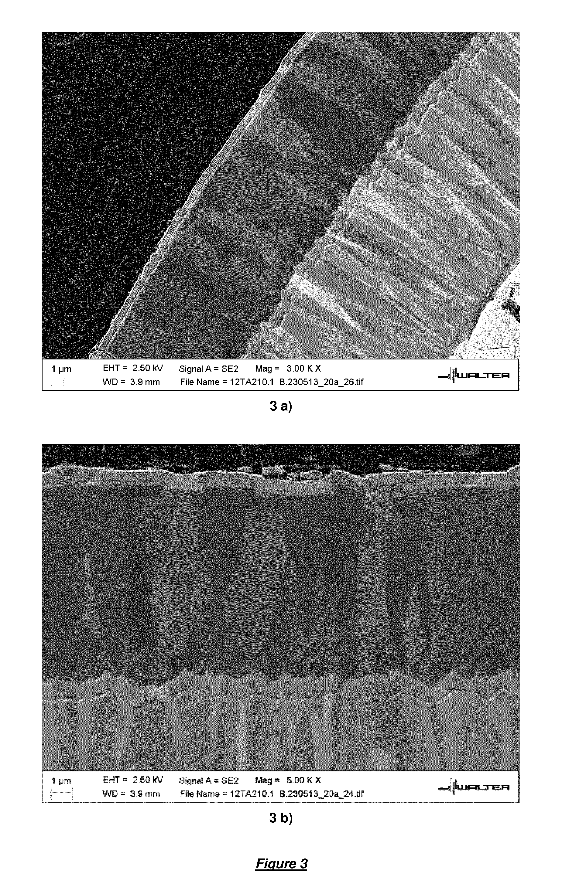
[0109]The α-Al2O3 coatings 3.1 and 3.2 were analysed by SEM. Cross-section microphotographs of coating 3.2 on the cutting edge and on the rake face, respectively, are shown in FIGS. 3a) and 3b). The cross-sectional images of FIGS. 3a) and 3b) clearly show the extreme smoothness of the surfaces of the α-Al2O3 layer, as well as of the top coating. A cross-section microphotograph of coating 3.1 according to the prior art is shown in FIG. 4. It clearly shows the significantly rougher surface due to the different faceting of the α-Al2O3 grains.


PUM

PropertyMeasurementUnit
Temperatureaaaaaaaaaa
Lengthaaaaaaaaaa

Abstract

A coated cutting tool insert includes a substrate of cemented carbide, cermet, ceramics, steel or cubic boron nitride having deposited thereon a coating having a total thickness of 60 μm, including one or more layers having a wear resistant layer of α-Al2O3 of a thickness of 1 to 45 μm deposited by chemical vapour deposition (CVD). The α-Al2O3 layer includes at least two portions, a first thickness portion and a second thickness portion immediately on top of the first thickness portion. The first thickness portion has an essentially columnar α-Al2O3 grain structure, and at a transition from the first thickness portion to the second thickness portion the grain boundaries of at least 1 out of 25 neighboring grains of the α-Al2O3 grains undergo a directional change into a direction that is essentially perpendicular, 90±45 degrees, to the grain boundaries in the first thickness portion.

Description

FIELD OF THE INVENTION[0001]The present invention relates to a coated cutting tool insert and a method of manufacturing the same, the coated cutting tool insert consisting of a substrate comprising cemented carbide, cermet, ceramics, steel or cubic boron nitride at least partially coated with a coating of a total thickness of a maximum of 60 μm consisting of one or more layers comprising a wear resistant layer of α-Al2O3 of a thickness of 2 to 45 μm deposited by chemical vapour deposition (CVD).BACKGROUND OF THE INVENTION[0002]The control of the α-Al2O3 polymorph in industrial scale was achieved in the beginning of the 1990's with commercial products based on U.S. Pat. No. 5,137,774. U.S. Pat. No. 5,654,035, U.S. Pat. No. 5,980,988, U.S. Pat. No. 7,442,431 and U.S. Pat. No. 5,863,640 describe the deposition of α-Al2O3 coatings with preferred fiber textures. U.S. Pat. No. 6,333,103 describes a modified method to control the nucleation and growth of α-Al2O3 on the (1 0 10) plane. U.S....

Claims


Application Information

Patent Timeline
IPC IPC(8): B23B27/14C30B29/68C30B29/20C23C16/40C30B25/18
CPCB23B27/148C23C16/403C30B25/18C30B29/20B23B2224/04B23B2228/04B23B2228/08B23B2222/28C30B29/68C23C16/45557C23C28/044C23C30/005B23B27/14C23C16/40C23C16/44
Inventor RUPPI, SAKARIENGSTROM, HINDRIKLAURIDSEN, JONASALM, OSCARMATSSON, PETERLARSSON, TOMMYLINDAHL, ERIKENGQVIST, JANSTIENS, DIRK
Owner SANDVIK INTELLECTUAL PROPERTY AB
Why Eureka
Try Eureka