Air conditioning system and control method thereof

a technology of air conditioning system and control method, which is applied in ventilation system, lighting and heating apparatus, heating types, etc., can solve the problems of complex structure of the overall system, sharp increase in electricity demand, and instability of the electricity supply system, so as to improve the efficiency of the heat pump and improve the energy efficiency of the operation mode.

Active Publication Date: 2017-01-19
KOREA INST OF SCI & TECH
View PDF5 Cites 19 Cited by
  • Summary
  • Abstract
  • Description
  • Claims
  • Application Information

AI Technical Summary

Benefits of technology

[0013]One or more embodiments include an air conditioning system which may perform various operation modes with a simple and compact structure by using a minimum number of elements such as a heat and mass exchanger and a heat exchange unit, and a controlling method thereof.
[0015]One or more embodiments include an air conditioning system which may include a heat and mass exchanger and a heat exchange unit (elements of a heat pump) and thus efficiency of the heat pump is improved through the operation of the heat and mass exchanger.
[0016]One or more embodiments include an air conditioning system which may improve energy efficiency of operation modes such as a ventilation cooling mode and a ventilation heating mode performed by a heat and mass exchanger, by changing the installation position with respect to the heat and mass exchanger and the number of the heat exchange units comprising the heat pump.

Problems solved by technology

Since the air conditioning system generally uses electric power, concurrent usage of the air conditioning system particularly in the summer season results in a sharp increase in the electricity demand which may cause instability in the electricity supply system.
However, since additional parts are needed, the structure of an overall system is complicated and manufacturing costs are increased.
Accordingly, it is not desirable to adopt both components of the enthalpy exchanger and the desiccant wheel in a single air conditioning system because the system would be too bulky.
However, according to the technology, the recovery of ventilation energy during a ventilation operation may not be performed.
For customers, it is quite inconvenient to purchase, install, and maintain multiple apparatuses, each having only a single function.

Method used


Image

  • Air conditioning system and control method thereof
  • Air conditioning system and control method thereof
  • Air conditioning system and control method thereof

Examples


Embodiment Construction

[0049]Reference will now be made in detail to embodiments, examples of which are illustrated in the accompanying drawings, wherein like reference numerals refer to like elements throughout. In this regard, the present embodiments may have different forms and should not be construed as being limited to the descriptions set forth herein. Accordingly, the embodiments are merely described below, by referring to the figures, to explain aspects of the present description. Expressions such as “at least one of,” when preceding a list of elements, modify the entire list of elements and do not modify the individual elements of the list.

[0050]Hereinafter, the structure and operation of air conditioning systems according to embodiments, and a controlling method thereof, are described in detail with reference to the accompanying drawings.

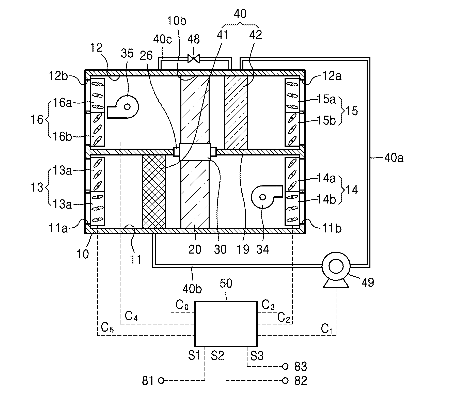
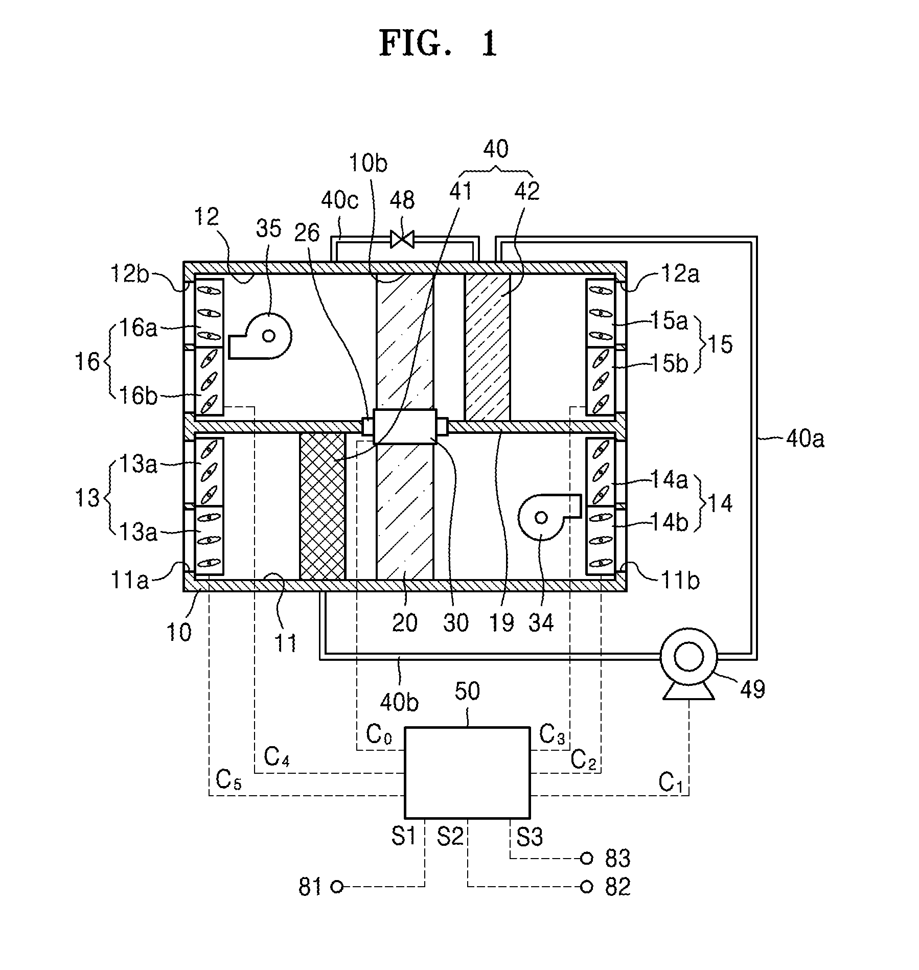
[0051]FIG. 1 is a conceptual diagram schematically illustrating a connection relation of elements of an air conditioning system according to an embodiment.

[0052...


PUM


Abstract

An air conditioning control system includes a casing including paths through which air passes, dampers arranged at an entrance and an exit of each of the paths and operated to open or close the entrance and the exit according to a control signal, a heat and mass exchanger including a hygroscopic material for absorbing moisture and arranged across the paths to be rotated with respect to the casing, a driving unit rotating the heat and mass exchanger, a heat exchange unit having a heat transfer medium flowing inside the heat exchange unit and arranged on at least one of the paths, and a controller opening or closing the entrance and the exit of the paths by applying a control signal to the dampers, and changing a rotation speed of the heat and mass exchanger by applying a control signal to the driving unit, according to operation modes.

Description

CROSS-REFERENCE TO RELATED APPLICATION[0001]This application claims the benefit of Korean Patent Application No. 10-2015-0100511, filed on Jul. 15, 2015, in the Korean Intellectual Property Office, the disclosure of which is incorporated herein in its entirety by reference.BACKGROUND[0002]1. Field[0003]One or more embodiments relate to an air conditioning system and a control method thereof, and more particularly, to an air conditioning system which may selectively perform various operation modes by performing both functions of a desiccant wheel and an enthalpy exchanger, using a single component, by changing a rotation speed of a heat and mass exchanger, and a control method thereof.[0004]2. Description of the Related Art[0005]An air conditioning system performs a cooling operation or a heating operation by controlling temperature and humidity in a sectioned space or a ventilation operation by discharging indoor air and supplying outdoor air.[0006]The air conditioning system is wid...

Claims


Application Information

Patent Timeline
Patent Type & Authority Applications(United States)
IPC IPC(8): F24F12/00F24F11/00F24F13/15F24F7/08F28F27/00F24F3/14
CPCF24F12/006F28F27/006F24F3/1423F24F13/15F24F7/08F24F11/0076F24F2011/0057F24F11/0015F24F11/0017F24F2203/1016F24F2203/1084F24F2203/1032F24F2011/0045F24F11/0012F24F11/62F24F11/30F24F3/1411F24F13/08F24F13/20F24F13/30F24F11/65F24F11/56F24F11/84F24F2140/00F24F11/77F24F11/46F24F2110/10F24F2110/20F24F2110/50F24F2140/20F24F2120/20F24F11/70Y02B30/56Y02B30/70
Inventor LEE, DAE YOUNG
Owner KOREA INST OF SCI & TECH
Why Eureka
Try Eureka