
Furnace cooling panel monitoring system
a technology for monitoring systems and cooling panels, applied in the direction of manufacturing converters, furniture, lighting and heating apparatus, etc., can solve problems such as maintenance and/or performance problems of flow rate sensors, and achieve the effects of high heat energy dissipation flux rate, high change rate, and quick increase in heat energy dissipation ra
- Summary
- Abstract
- Description
- Claims
- Application Information
AI Technical Summary
Benefits of technology
Problems solved by technology
Method used
Image

Examples
Embodiment Construction
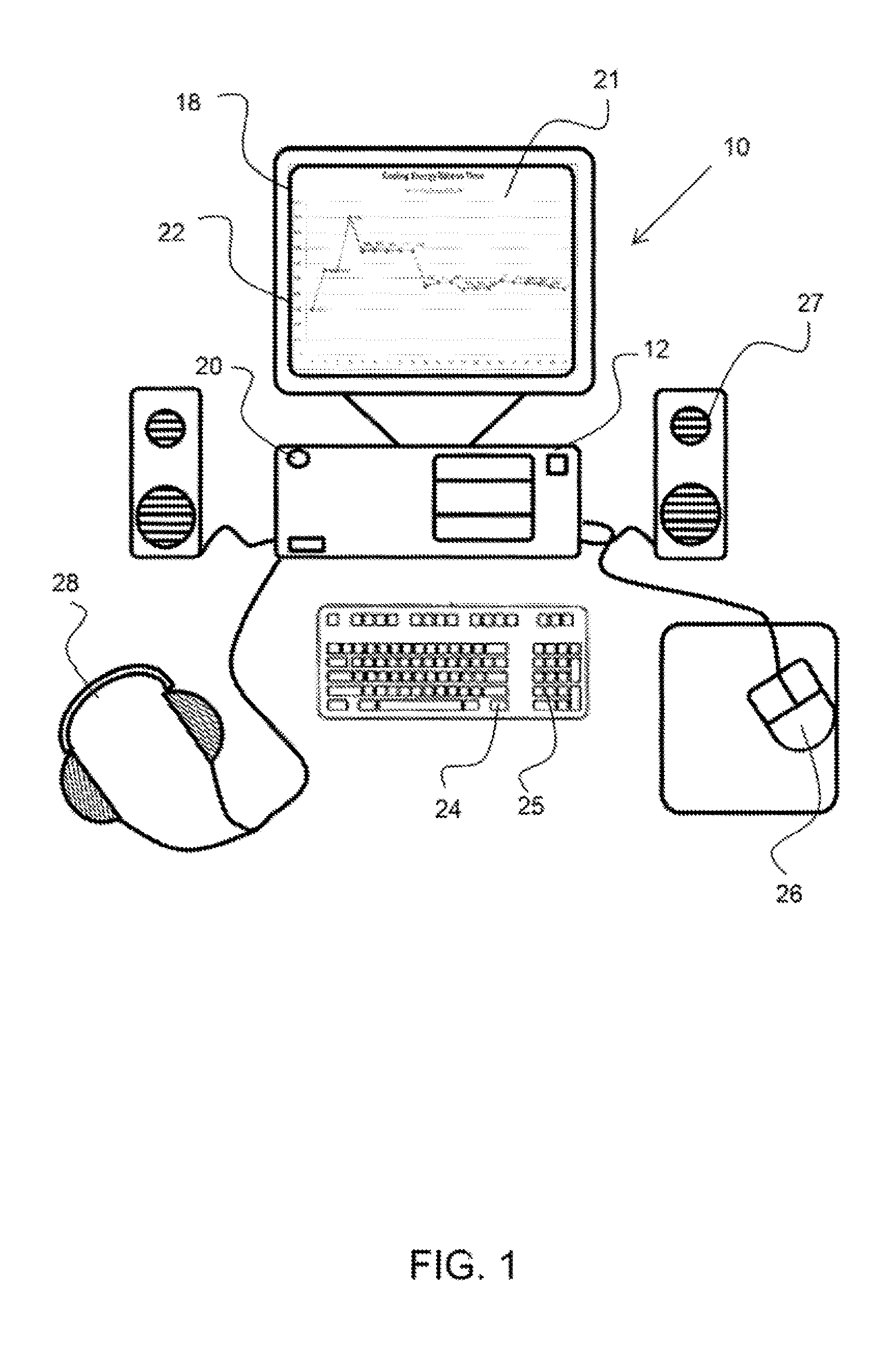
[0022]FIG. 1 shows an exemplary monitoring station for a furnace cooling panel monitoring system, as described herein.
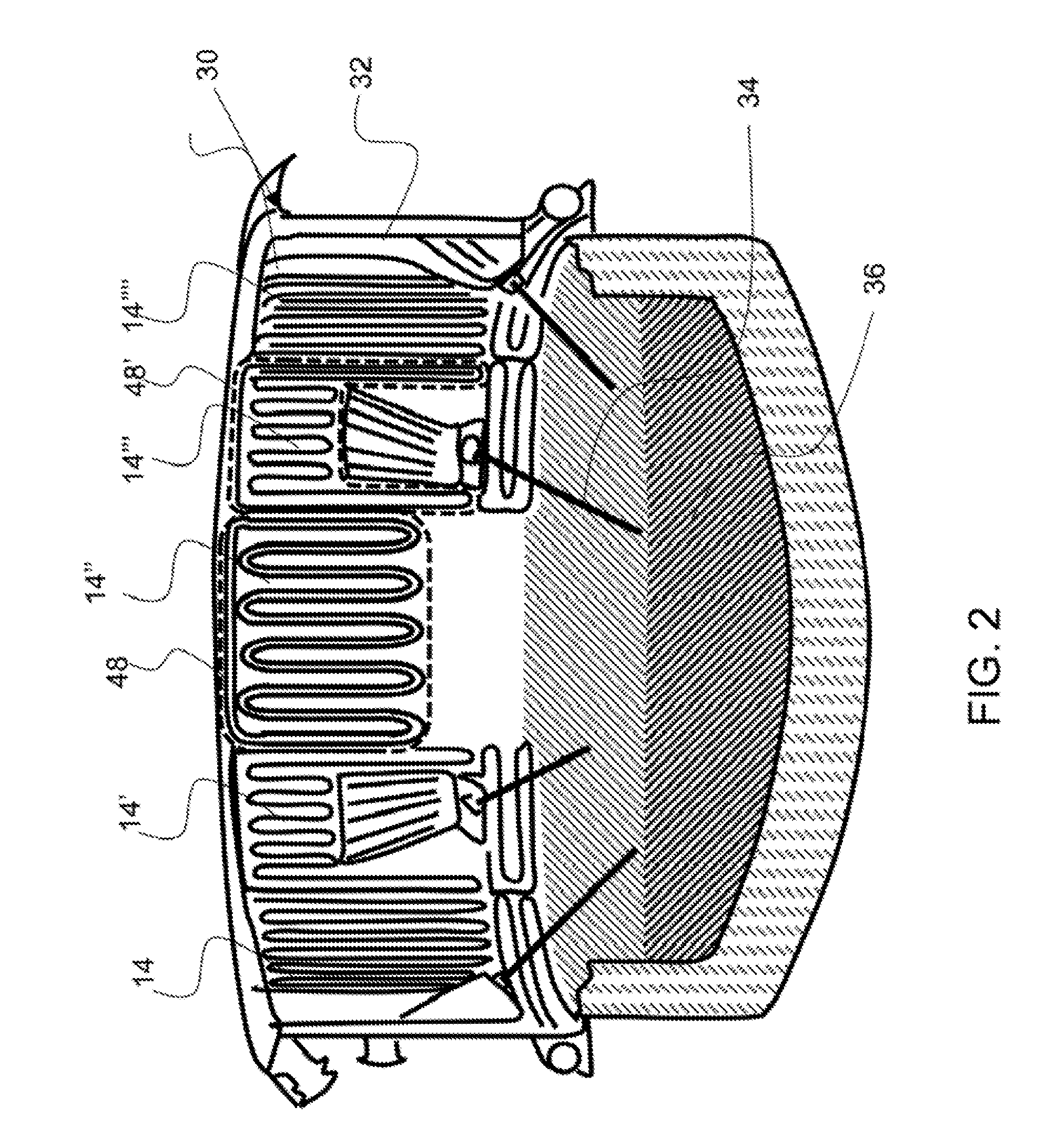
[0023]FIG. 2 shows an exemplary electric arc furnace having a plurality of cooling panels.
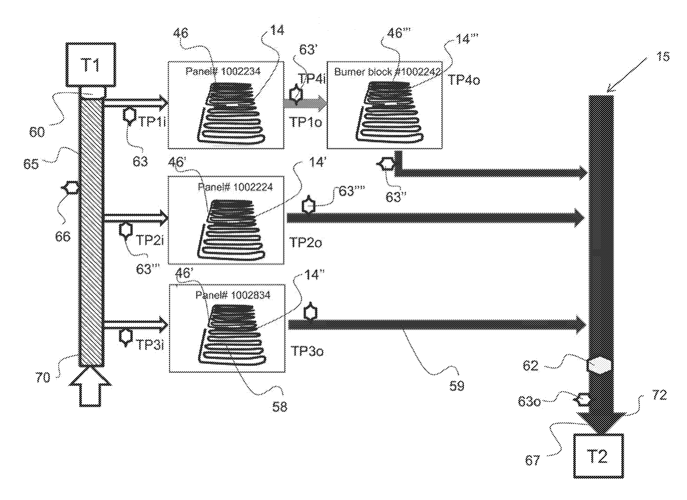
[0024]FIG. 3 shows a diagram of a cooling panel array comprising a plurality of individual cooling panels configured between an array cooling fluid inlet and an array cooling fluid outlet.
[0025]FIG. 4 shows a graph of pressure drop versus flow rate for an exemplary panel and an associated K value.
[0026]FIG. 5 shows an exemplary display chart of panel heat energy dissipation rates as a function of time.
[0027]FIG. 6 shows an exemplary display graph of heat energy dissipation rates as a function of time with a threshold value that is being surpassed by one of the cooling panels.
[0028]FIG. 7 shows an exemplary display graph of heat energy dissipation rate as a function of time.
[0029]FIG. 8 shows an exemplary heat map display diagram of cooling panels configured around a furnace.
[003...
PUM
| Property | Measurement | Unit |
|---|---|---|
| Time | aaaaa | aaaaa |
| Flow rate | aaaaa | aaaaa |
| Dissipation factor | aaaaa | aaaaa |
Abstract
Description
Claims
Application Information