
Method and apparatus of back lobe correction to antenna temperature for earth-observing microwave instruments

a microwave instrument and antenna temperature technology, applied in error detection/correction, instruments, computing, etc., can solve the problems of electromagnetic radiation detection, diffraction limitation, and relatively poor resistance to radiation from celestial bodies, so as to reduce the uncertainty of galactic correction

Inactive Publication Date: 2017-01-19
NASA
View PDF6 Cites 7 Cited by
  • Summary
  • Abstract
  • Description
  • Claims
  • Application Information

AI Technical Summary

Benefits of technology

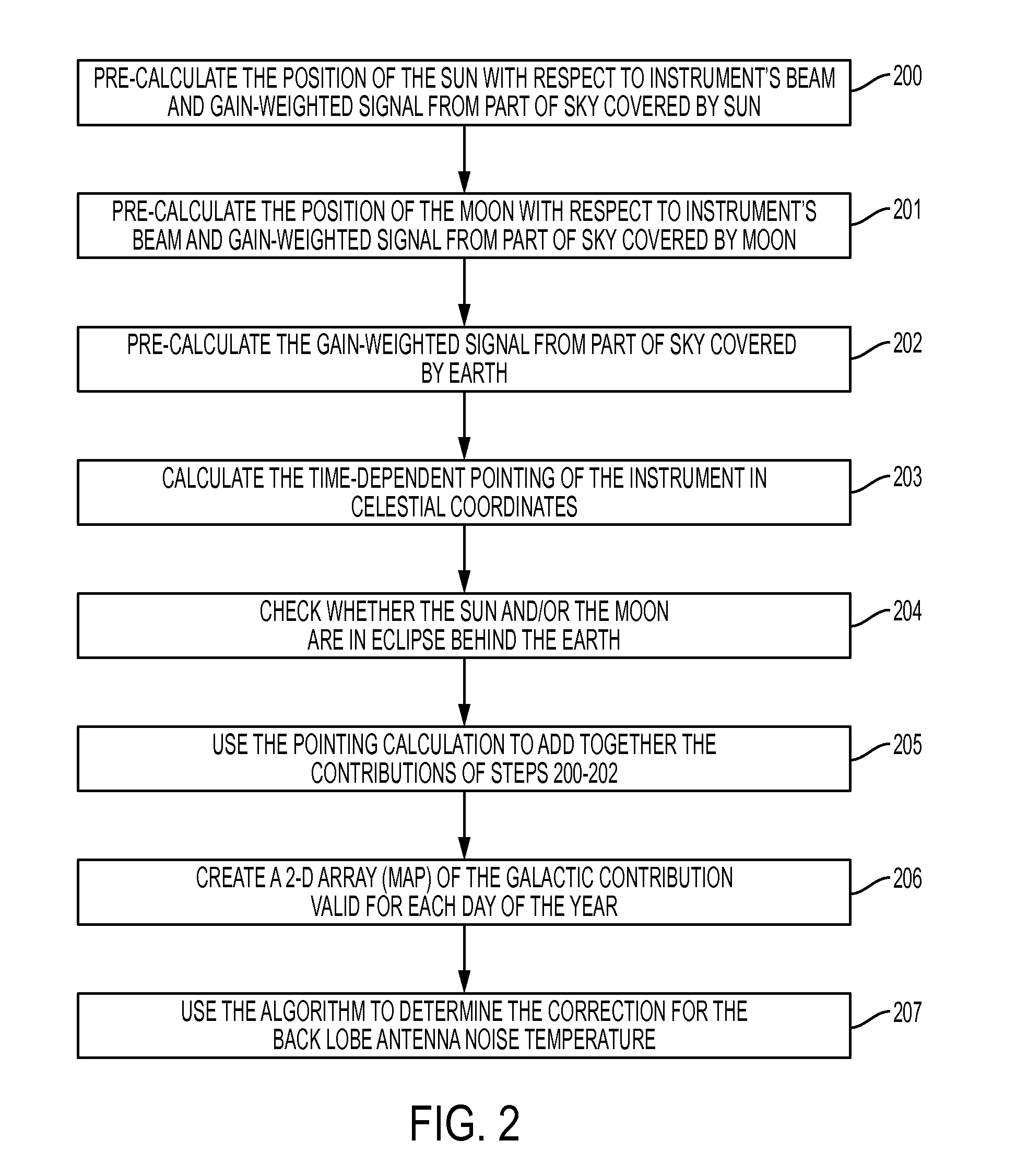
The present invention allows for the pre-calculation of all outputs, which simplifies the program's final step of dealing with the last variable (i.e. time-dependent pointing). However, the invention only requires a small handful of outputs: one for the Sun, one for the Moon, and a few for the Galaxy. The accuracy of the correction can be improved by averaging together multiple output files for different angles. Using all 10 outputs and interpolating between adjacent ones can reduce uncertainty in the Galactic correction to a few milli-Kelvin levels.

Problems solved by technology

Microwave antennas deployed for space-borne instruments such as radiometers, which detect electromagnetic radiation, are diffraction-limited, with typical beam efficiency which characterizes the antennas' performance, of about 90%, and which provide relatively poor resistance to radiation from celestial bodies (i.e., Moon, Sun, Galaxy), when they are at the side or back of the radiometer.
The program runs (i.e., data files) are dynamic with time, and this approach is time consuming as it introduces an additional source of uncertainty when maps calculated for one orbit at the beginning of the mission are applied to the same orbit many months after launch when positional data may have changed, and thus, may need to be recalculated if, for example, the equatorial crossing time differs from the planned one.

Method used


Image

  • Method and apparatus of back lobe correction to antenna temperature for earth-observing microwave instruments
  • Method and apparatus of back lobe correction to antenna temperature for earth-observing microwave instruments
  • Method and apparatus of back lobe correction to antenna temperature for earth-observing microwave instruments

Examples


Embodiment Construction

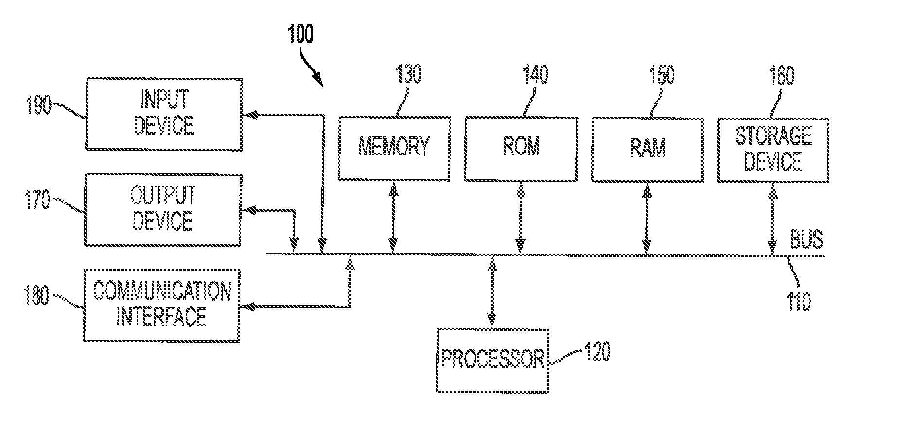
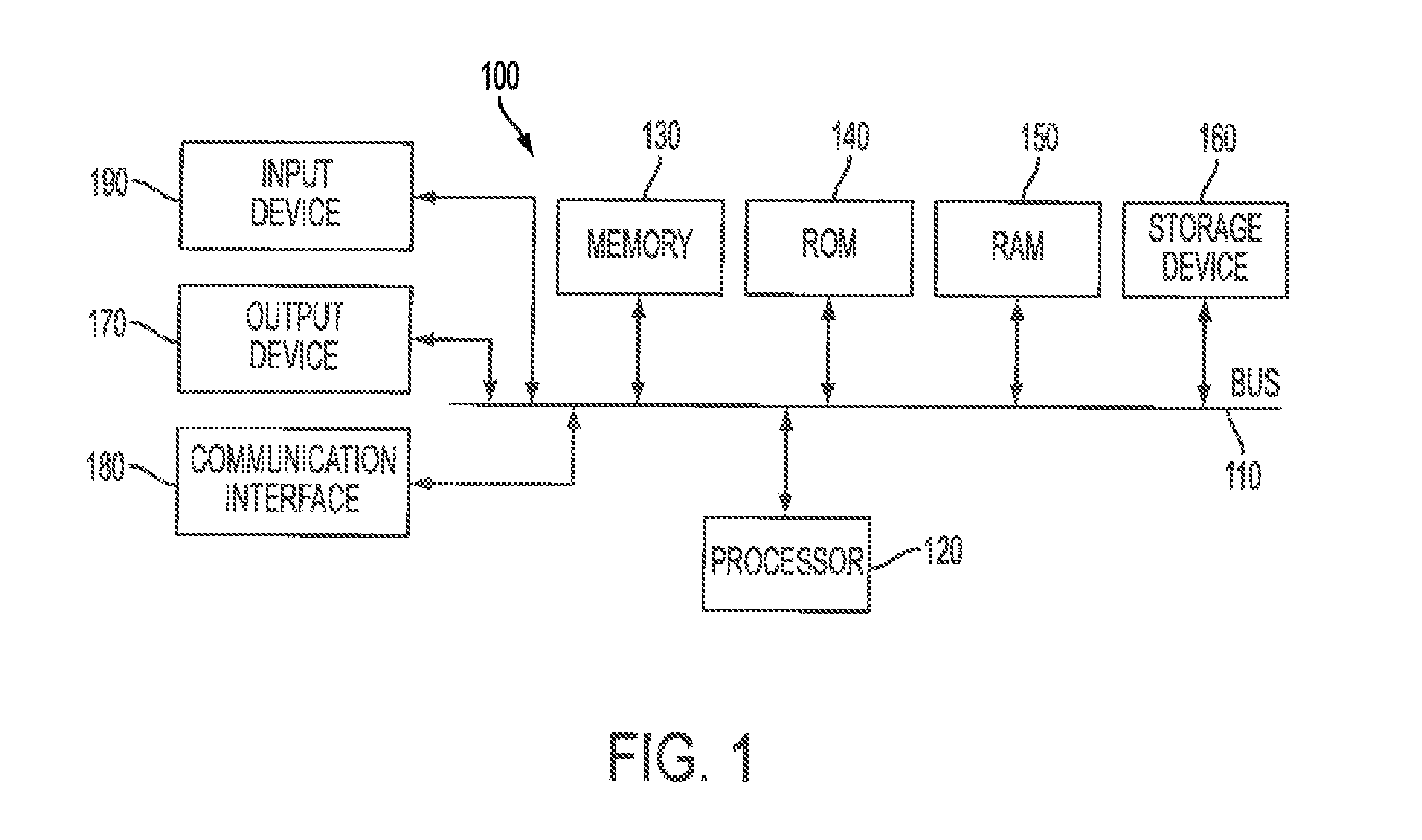
[0038]With reference to FIG. 1, an exemplary system includes a general-purpose computing device 100, including a processing unit (CPU) 120 and a system bus 110 that couples various system components including the system memory, such as read-only memory (ROM) 140 and random access memory (RAM) 150 to the processing unit 120. Other system memory 130 may be available for use as well. It can be appreciated that the invention may operate on a computing device with more than one CPU 120 or on a group or cluster of computing devices networked together to provide greater processing capability. A processing unit 120 can include a general purpose CPU controlled by software as well as a special-purpose processor. An Intel® Xeon LV L7345 processor is an example of a general purpose CPU which is controlled by software. Particular functionality may also be built into the design of a separate computer chip. An STMicroelectronics STA013 processor is an example of a special-purpose processor which d...


PUM


Abstract

The present invention relates to a method and apparatus which corrects antenna noise temperature in antenna back lobes, for earth-observing microwave instruments on satellites in orbit, to counter signal contamination from celestial bodies. The antenna back lobe signal correction is computer-program-modeled with only a few static and only a few dynamic inputs, and for a given set of parameters (i.e., orbital altitude, pointing characteristics (e.g., nadir or cross-scanning or conical-scanning), frequency selectivity of the receiver / detector) produces a few output files which are then combined by the program to predict the back lobe signal correction which is to be applied.

Description

BACKGROUND OF THE INVENTION[0001]1. Field of the Invention[0002]The present invention relates to a method and apparatus of back lobe correction to antenna temperature for earth-observing microwave instruments to counter extra-terrestrial signal contamination.[0003]2. Description of the Related Art[0004]Microwave antennas deployed for space-borne instruments such as radiometers, which detect electromagnetic radiation, are diffraction-limited, with typical beam efficiency which characterizes the antennas' performance, of about 90%, and which provide relatively poor resistance to radiation from celestial bodies (i.e., Moon, Sun, Galaxy), when they are at the side or back of the radiometer.[0005]Traditionally, this signal contamination, which increases antenna temperature, has been removed by using computer programs with algorithms which are run multiple times (i.e., multiple data files), and which represent the relative position of the spacecraft and the celestial sources throughout th...

Claims


Application Information

Patent Timeline
IPC IPC(8): G06F11/00
CPCG06F11/00G01S7/4021
Inventor DE AMICI, GIOVANNI
Owner NASA
Learn More