Short wavelength visible light-emitting toothbrush with an electronic signal interlock control
a technology of electronic signal and visible light, which is applied in the field of short wavelength visible lightemitting toothbrushes with electronic signal interlock control, can solve the problems of inability to achieve energy levels, eye damage, safety risks, etc., and achieve the effect of increasing the safety of dental hygiene implements
- Summary
- Abstract
- Description
- Claims
- Application Information
AI Technical Summary
Benefits of technology
Problems solved by technology
Method used
Image
Examples
embodiment 130
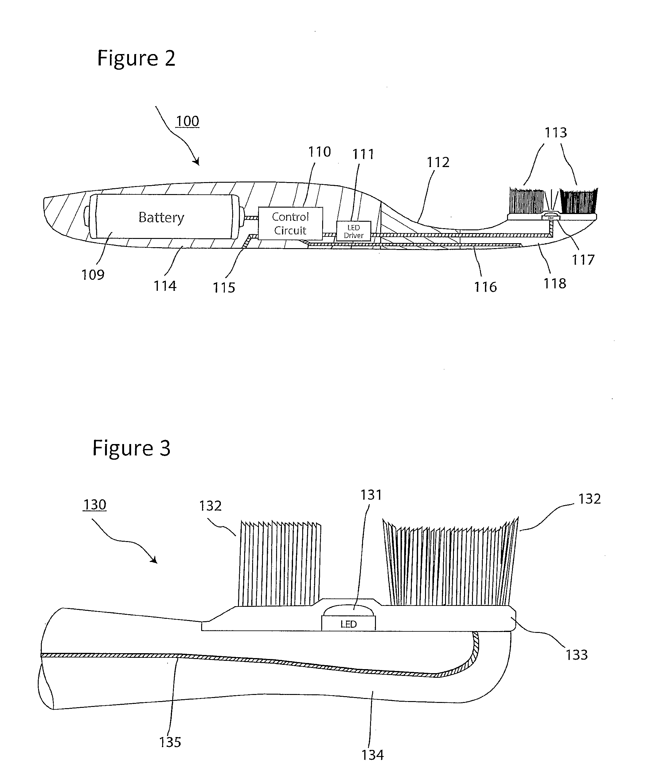
[0117]In an alternate embodiment 130 shown in FIG. 3, conductive plastic is used in the part 133 of the brush connecting the bristles 132 to a sheet of conductive plastic 133, instead of the entire brush head. Alternatively, but also possibly in combination, as shown in FIG. 3, the bristles 132 of the brush may also be conductive. When wet bristles 132 come in contact with the mouth of the user during normal brushing operations a circuit is formed via a sense electrode 135 connected to the control circuit 110, which can be used to detect the completion of the electrical signal loop and signals the driver 111 to supply electricity to the LED 131. The remainder of the brushhead 134, is composed of non-conductive plastic.
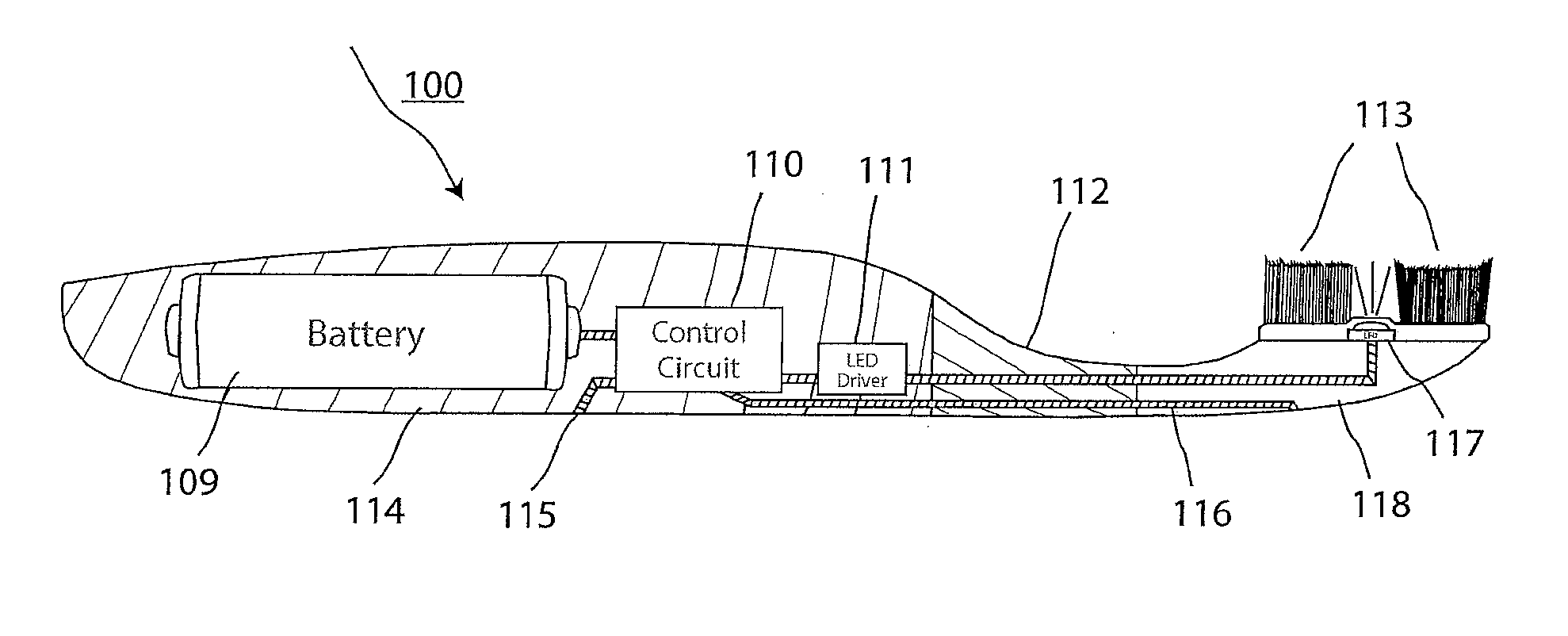
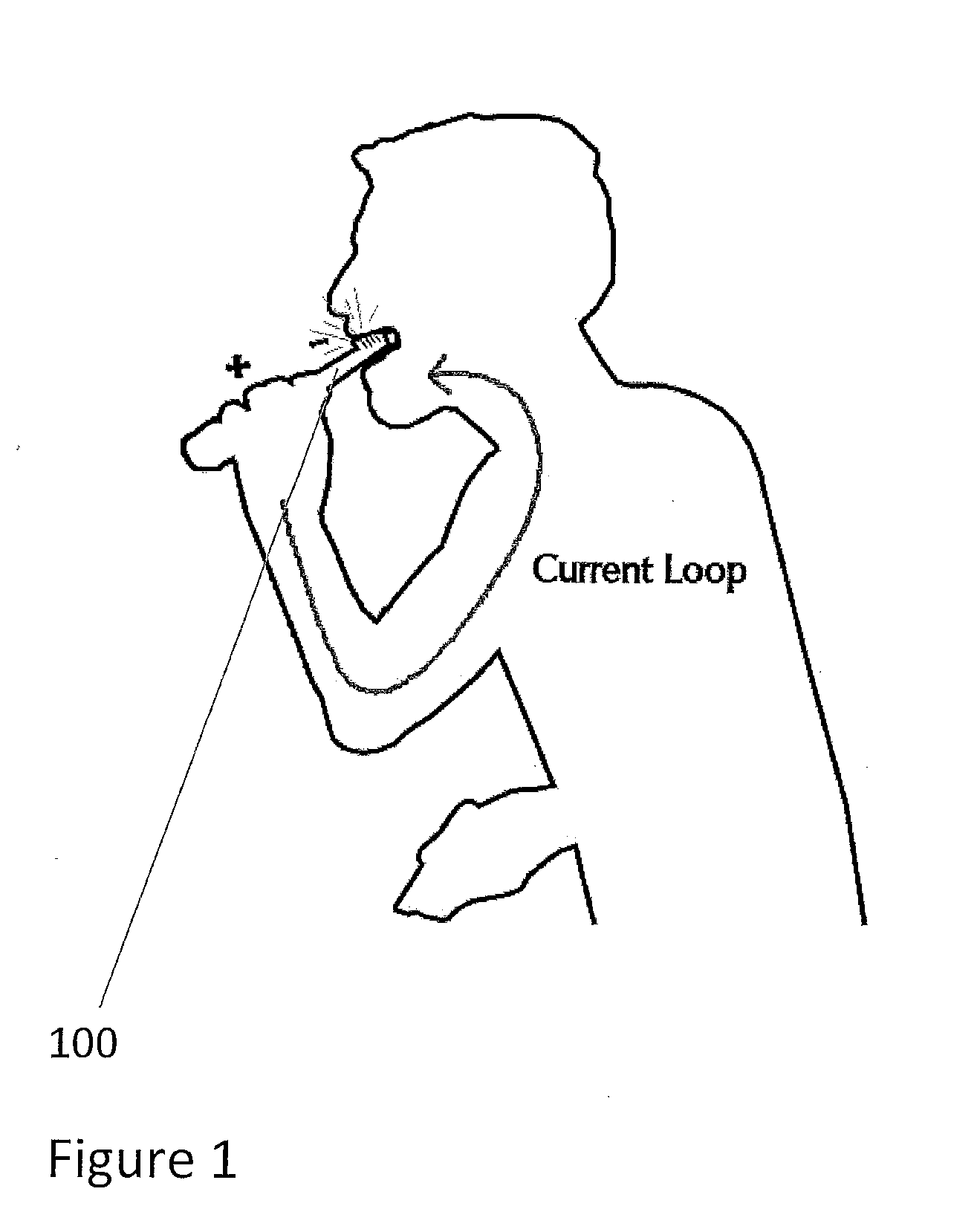
[0118]Typically when brushing teeth, a user will grasp the handle 114 of toothbrush 100, apply toothpaste to the bristles 113 and place the brush head 118 in the mouth and proceed to brush their teeth. While the toothbrush handle 114 is in contact with the user's hand ...
embodiment 160
[0122]A further embodiment 160 is shown in FIG. 5. The handle has a portion 161 of conductive plastic, and the head has a portion 162 of conductive plastic. Portion 163 is non-conductive. The conductive plastic areas are connected internally to circuits as described in connection with FIG. 2 and so the toothbrush of FIG. 5 can be used in like manner to the toothbrush of FIG. 2.
[0123]Many electric toothbrushes employ a timer to alert the user of the end of a preset brushing time, for example, two minutes, as recommended by the American Dental Association. These timer circuits are commonly combined with vibration or noise to alert the end user to the completion of a recommended brushing period. The signal loop sensor disclosed herein can be combined with such a timing circuit in a manner that causes elapsed time to be recorded only when the sensor is activated (i.e. light is on). This would facilitate the assurance that the brush timer was actually measuring elapsed time in the mouth ...
first embodiment
[0210]As in the previous embodiment, the toothbrush 1126 includes an automatic mode of operation. To facilitate the automatic mode of operation, the toothbrush 1126 has a first switch (not shown) that is configured as in the previous embodiment. A second switch 1146, seen in FIGS. 59 and 61, includes a contact plate 1148 having legs 1150 and a contact rod 1152. The contact plate 1148 and the contact rod 1152 are disposed within the handle portion 1128 and are covered by a seal 1154. Similar to the contact plates 1070, 1072 used in the first embodiment, the contact plate 1148 and the contact rod 1152 are wired to a PC board (not shown).
[0211]The method by which the removable head portion 1132 attaches to the handle portion 1128 is also different from the first embodiment. An adaptor 1156, seen in FIGS. 60 and 61, is located inside the housing 1136 of the removable head portion 1132, and snaps into recesses 1157 in the handle portion 1128, (see FIG. 60). This attachment allows the rem...
PUM
 Abstract
Description
Claims
Application Information
 - R&D
- Intellectual Property
- Life Sciences
- Materials
- Tech Scout
- Unparalleled Data Quality
- Higher Quality Content
- 60% Fewer Hallucinations
Browse by: Latest US Patents, China's latest patents, Technical Efficacy Thesaurus, Application Domain, Technology Topic, Popular Technical Reports.
© 2025 PatSnap. All rights reserved.Legal|Privacy policy|Modern Slavery Act Transparency Statement|Sitemap|About US| Contact US: help@patsnap.com


