Thermal control device and methods of use

a control device and control method technology, applied in the direction of lighting and heating apparatus, machines using electric/magnetic effects, refrigerating machines, etc., can solve the problems of increasing space and power requirements, lag and overlap problems that are often worse, and not operating with rapid digital-like precision, etc., to achieve the effect of increasing speed and efficiency

Active Publication Date: 2017-01-26
CEPHEID INC
View PDF1 Cites 23 Cited by
  • Summary
  • Abstract
  • Description
  • Claims
  • Application Information

AI Technical Summary

Benefits of technology

[0026]In some embodiments, the thermal control device includes a first thermoelectric cooler having an active face and a reference face, a thermal manipulation device, a thermal interposer disposed between the first thermoelectric coolers and the thermal manipulation device such that the reference face of the first thermoelectric cooler is thermally coupled with the thermal manipulation device through the thermal interposer, and a first temperature sensor adapted to sense the temperature of the active face of the first thermoelectric cooler. The device can further include a controller operatively coupled to eac...

Problems solved by technology

Fan based cooling systems have issues with start-up lag time and shutdown overlap, that is, they will function after being shut off and thus do not operate with rapid digital-like precision.
Such lag and overlap issues frequently become worse with device age.
The answer thus far has been to incorporate more powerful fans having greater volumetric output rates, which also increase space and power requirements.
One price of this is a negative effect on portability of field testing systems, which can be used, for example, to rapidly detect viral/bacterial outbreaks in outlying areas.
Another problem is that this approach is less successful in higher temperature environments, such as may be found in tropical regions.
Because of the large thermal mass of the aluminum block, heating and cooling rates are limited to about 1° C./sec, so that a fifty-cycle PCR process may require two or more hours to complete.
In tropical climates, where ambient temperatures can be elevated the cooling rates can be adversely e...

Method used


Image

  • Thermal control device and methods of use
  • Thermal control device and methods of use
  • Thermal control device and methods of use

Examples


Embodiment Construction

[0040]The present invention relates generally to systems, devices and methods for controlling thermal cycles in a chemical reaction, in particular, a thermal control device module adapted for use in controlling thermal cycling in a nucleic acid amplification reaction.

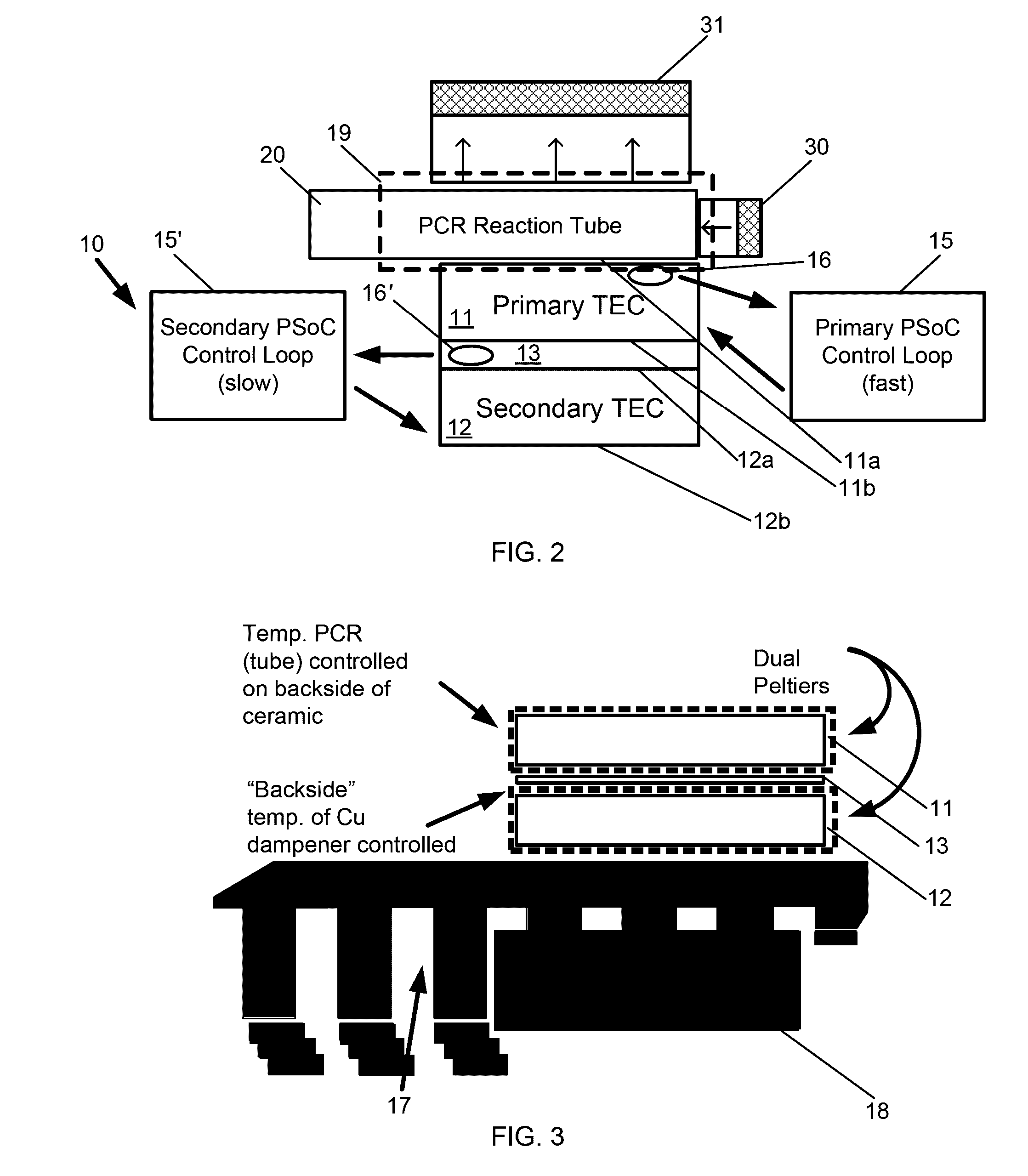
[0041]In a first aspect, the invention provides a thermal control device that provides improved control and efficiency in thermal cycling. In some embodiments, such thermal control devices can be configured to perform thermal cycling for a polymerase chain reaction of a fluid sample in the reaction vessel. Such devices can include at least one thermoelectric cooler positioned in direct contact with or immediately adjacent the reaction vessel so that a temperature of the active face of the thermoelectric cooler configurations corresponds to a temperature of the fluid sample with the reaction vessel. This approach assumes sufficient time for thermal conduction to equilibrate the temperature of the fluid sample within the ...


PUM


Abstract

Thermal control devices adapted to provide improved control and efficiency in temperature cycling are provided herein. Such thermal control device can include a thermoelectric cooler controlled in coordination with another thermal manipulation device to control an opposing face of the thermoelectric cooler and/or a microenvironment. Some such thermal control devices include a first and second thermoelectric cooler separated by a thermal capacitor. The thermal control devices can be configured in a planar configuration with a means for thermally coupling with a planar reaction vessel of a sample analyzer for use in thermal cycling in a polymerase chain reaction of the fluid sample in the reaction vessel. Methods of thermal cycling using such a thermal control devices are also provided.

Description

CROSS-REFERENCES TO RELATED APPLICATIONS[0001]This application claims the benefit of priority of U.S. Provisional Patent Application No. 62 / 196,267 entitled “Thermal Control Device and Methods of Use,” filed on Jul. 23, 2015; the entire contents of which are incorporated herein by reference.[0002]This application is generally related to U.S. patent application Ser. No. 13 / 843,739 entitled “Honeycomb tube,” filed on Mar. 15, 2013; U.S. Pat. No. 8,048,386 entitled “Fluid Processing and Control,” filed Feb. 25, 2002; and U.S. Pat. No. 6,374,684 entitled “Fluid Control and Processing System,” filed Aug. 25, 2000; each of which is incorporated herein by reference in its entirety for all purposes.BACKGROUND OF THE INVENTION[0003]The present invention relates generally to thermal control devices, more particularly to a device, system and methods for thermal cycling in a nucleic acid analysis.[0004]Various biological testing procedures require thermal cycling to facilitate a chemical reacti...

Claims


Application Information

Patent Timeline
IPC IPC(8): F25B21/04B01L7/00
CPCF25B21/04F25B2321/0212F25B2321/0251B01L7/52B01L2300/1822B01L2200/025
Inventor FROMM, DAVIDPHAN, TIENPICCINI, MATTHEW
Owner CEPHEID INC
Why Eureka
Try Eureka