Eureka AIR delivers breakthrough ideas for toughest innovation challenges, trusted by R&D personnel around the world.

Interferometric Ellipsometry and Method using Conical Refraction

Inactive Publication Date: 2017-01-26
ADOM ADVANCED OPTICAL TECH
View PDF5 Cites 1 Cited by
  • Summary
  • Abstract
  • Description
  • Claims
  • Application Information

AI Technical Summary

Benefits of technology

The present invention provides methods and systems for making parallel measurements without having to rotate the polarizer or analyzer. This is accomplished by using a biaxial birefringent crystal that intercepts and transforms light reflected from an object, creating a ring of light with a different polarization plane at each point along its periphery. This avoids the need for a rotating polarizer or analyzer. Additionally, the invention can create different rings of light with polarization planes rotating along each ring, which also eliminates the need for a spectrometer. The technical effects of the invention are improved accuracy and efficiency in measuring optical properties of various objects.

Problems solved by technology

However, using a monochromatic light source restricts the results to one set of ψ and Δ values per measurement.

Method used


Image

  • Interferometric Ellipsometry and Method using Conical Refraction
  • Interferometric Ellipsometry and Method using Conical Refraction
  • Interferometric Ellipsometry and Method using Conical Refraction

Examples


Embodiment Construction

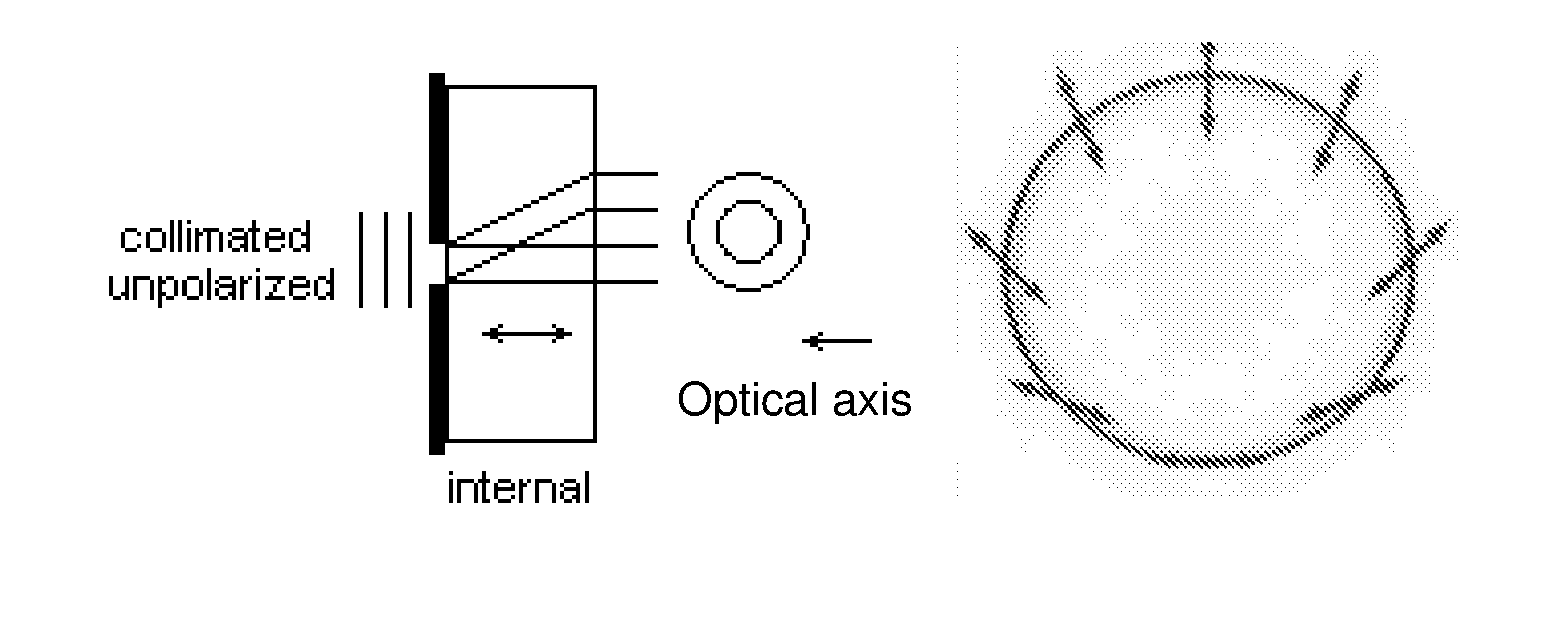
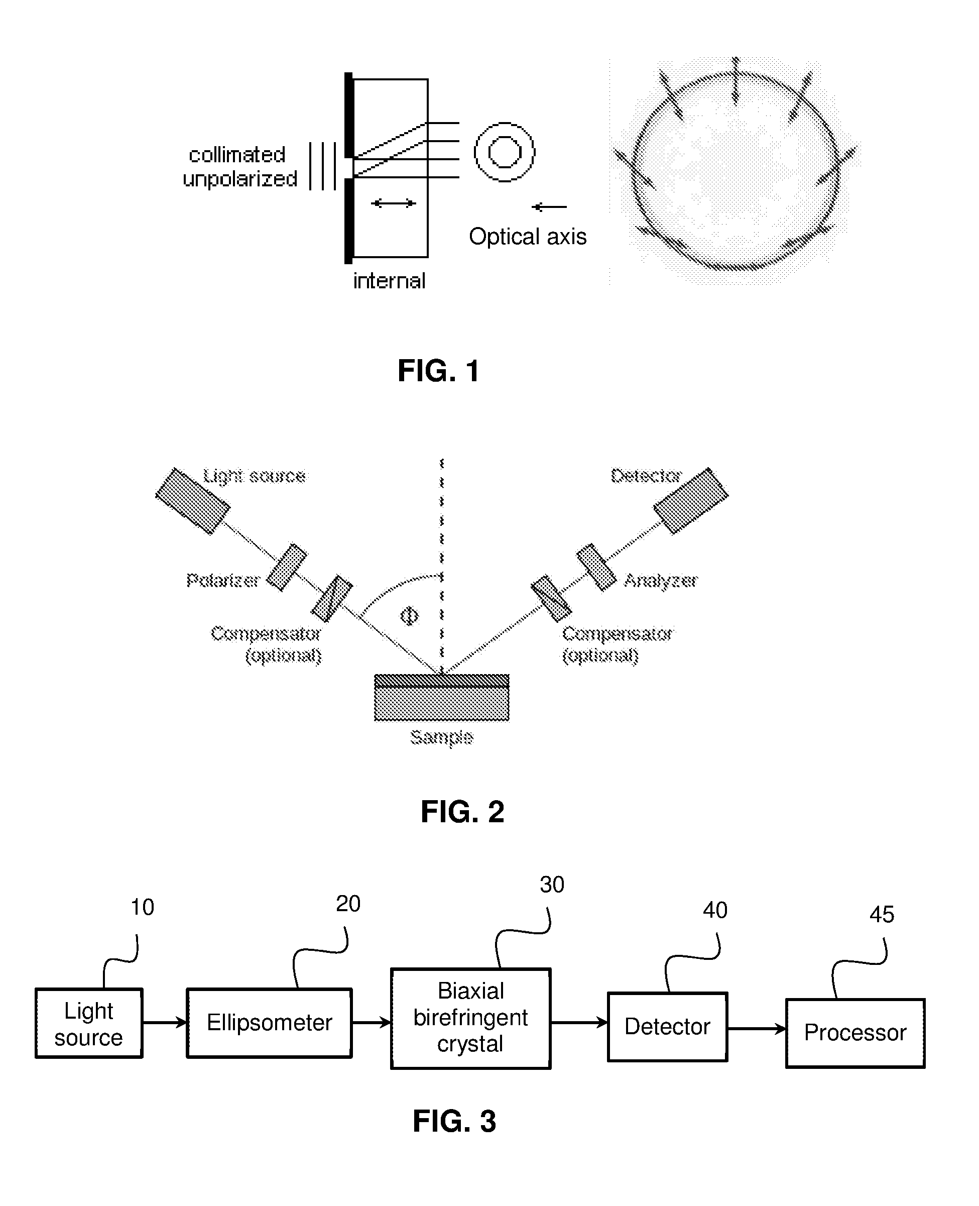
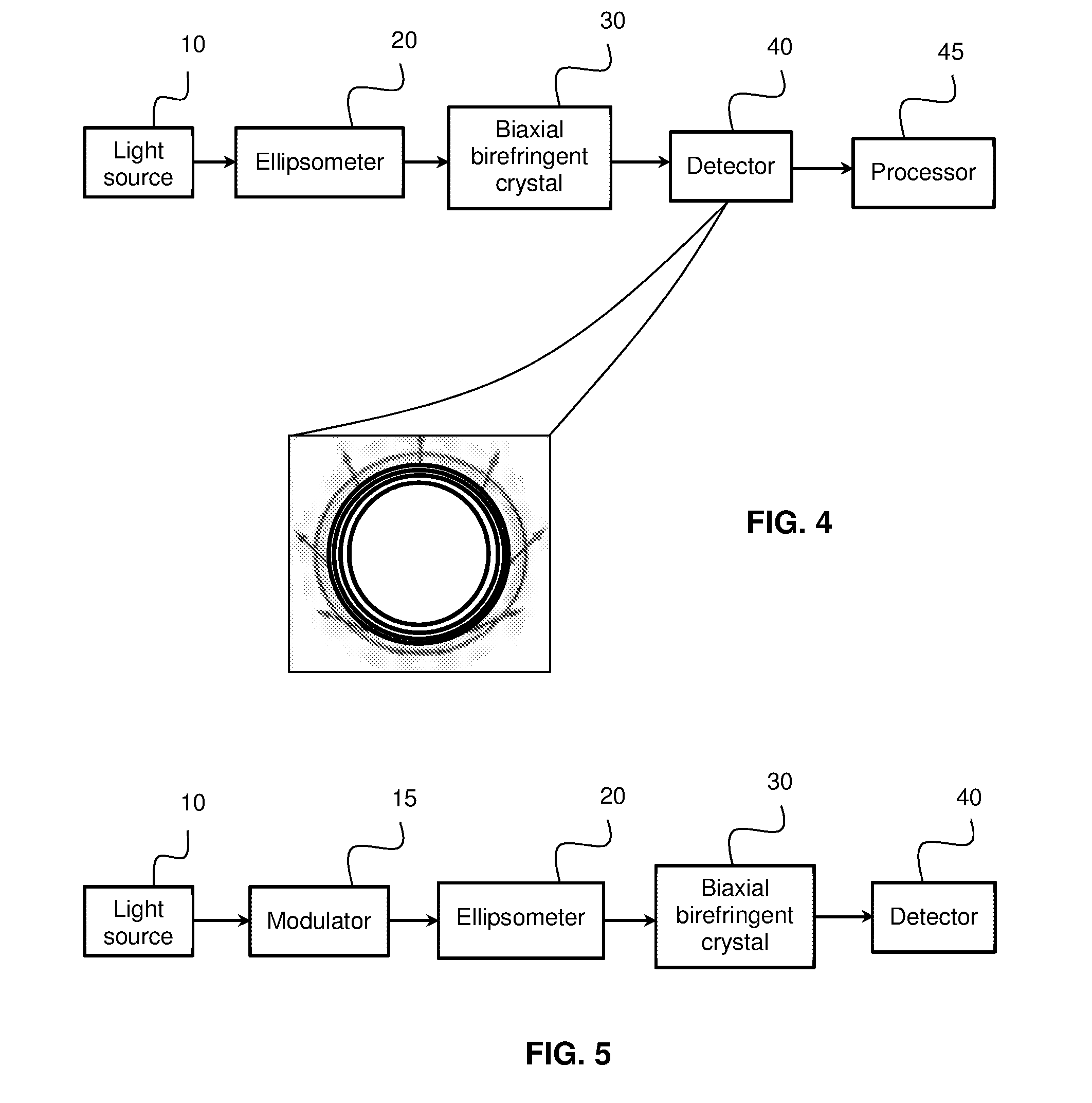
[0028]FIG. 3 shows one embodiment of the present invention in which a biaxial crystal is combined with an ellipsometer 20, constituting an optical system. The light source 10 of the ellipsometer may be a monochromatic light source. In this configuration, the analyzer in the ellipsometer is removed and the light reflected from the object is focused and it propagates along the optical axis of a biaxial birefringent crystal 30. The biaxial birefringent crystal propagates the reflected light and transforms in into a ring of light, such that each point along the periphery of the light ring is linearly polarized and whose polarization plane rotates along the ring. The ring of light is imaged either by propagation or by an optical system on to a detector array 40, which could be a CCD camera for example, to which there is coupled a processor 45 that processes the pattern imaged by the detector array 40 for obtaining an output indicating the object's optical properties. Since the polarizati...


PUM


Abstract

An apparatus and method for determining optical properties of an object (50) includes a light source (10) and an optical system for illuminating at least one point of the object with light from the light source, and collecting light reflected from the object. A biaxial birefringent crystal (30) intercepts a beam of light reflected from the object and propagates the beam along an optical axis of the crystal and transforms the beam of reflected light to a ring of light having a periphery, each point of which has a different polarization plane. A detector array (40) detects respective points along the periphery of the ring and a processing unit (45) is coupled to the detector and is responsive to signals thereby for determining optical properties of the object.

Description

FIELD OF THE INVENTION[0001]This invention relates to the use of conical refraction (CR) at a biaxial crystal for taking multi-polarizations ellipsometric measurements.BACKGROUND OF THE INVENTIONConical Refraction[0002]When a focused input Gaussian beam propagates along the optic axis of a biaxial crystal, it is transformed into a light ring, as shown in FIG. 1. The radius of the CR ring depends on the crystal's length and its principal refractive indices.[0003]One feature of the CR effect is that each point of the light ring is linearly polarized, with the polarization plane rotating along the ring so that every pair of diagonally opposite points has orthogonal polarizations. The biaxial crystal projects an input non-polarized beam into an infinite number of linearly polarized states.Ellipsometry[0004]Ellipsometry is an optical method for measuring a sample's properties such as thickness, complex refractive index or dielectric function tensor. The change of polarization of light up...

Claims


Application Information

Patent Timeline
IPC IPC(8): G01N21/21G01N21/45G01B9/02
CPCG01N21/211G01B9/02091G01N21/45G01N2201/06113G01N2021/213G01N2021/458G01B2290/70
Inventor ARIELI, YOELCOHEN, YOEL
Owner ADOM ADVANCED OPTICAL TECH
Why Eureka
Eureka Blog
Learn More