Method and system of thermographic non-destructive inspection for detecting and measuring volumetric defects in composite material structures

a non-destructive inspection and composite material technology, applied in the direction of structural/machine measurement, radiation pyrometry, instruments, etc., can solve the problems of local lack of uniformity, prejudice the result of inspection, and traditional thermography is affected by some limits

Active Publication Date: 2017-01-26
LEONARDO SPA
View PDF0 Cites 33 Cited by
  • Summary
  • Abstract
  • Description
  • Claims
  • Application Information

AI Technical Summary

Problems solved by technology

In fact, if the item is opportunely stimulated, by means of suitable lamps, the presence of a defect creates a change in the normal heat diffusion, causing local lack of uniformity in surface temperature distribution on the item under investigation, easily identifiable through the use of a thermographic camera.
On the other hand, traditional thermography is affected by some limits due to disturbances, such as non-uniform heating, reflections from heat sources in the working environment and non-homogeneous emissivity coefficients, which could be reproduced on the image of the item being tested and could therefore prejudice the result of the inspection.
The method divulged in that document does not allow thermographic inspection for “volumetric” defects (i.e. defects where none of length, width and depth can be overlooked), as are resin pockets that occur in composite material structures, for example in glass fibre or carbon fibre.

Method used


Image

  • Method and system of thermographic non-destructive inspection for detecting and measuring volumetric defects in composite material structures
  • Method and system of thermographic non-destructive inspection for detecting and measuring volumetric defects in composite material structures
  • Method and system of thermographic non-destructive inspection for detecting and measuring volumetric defects in composite material structures

Examples


Embodiment Construction

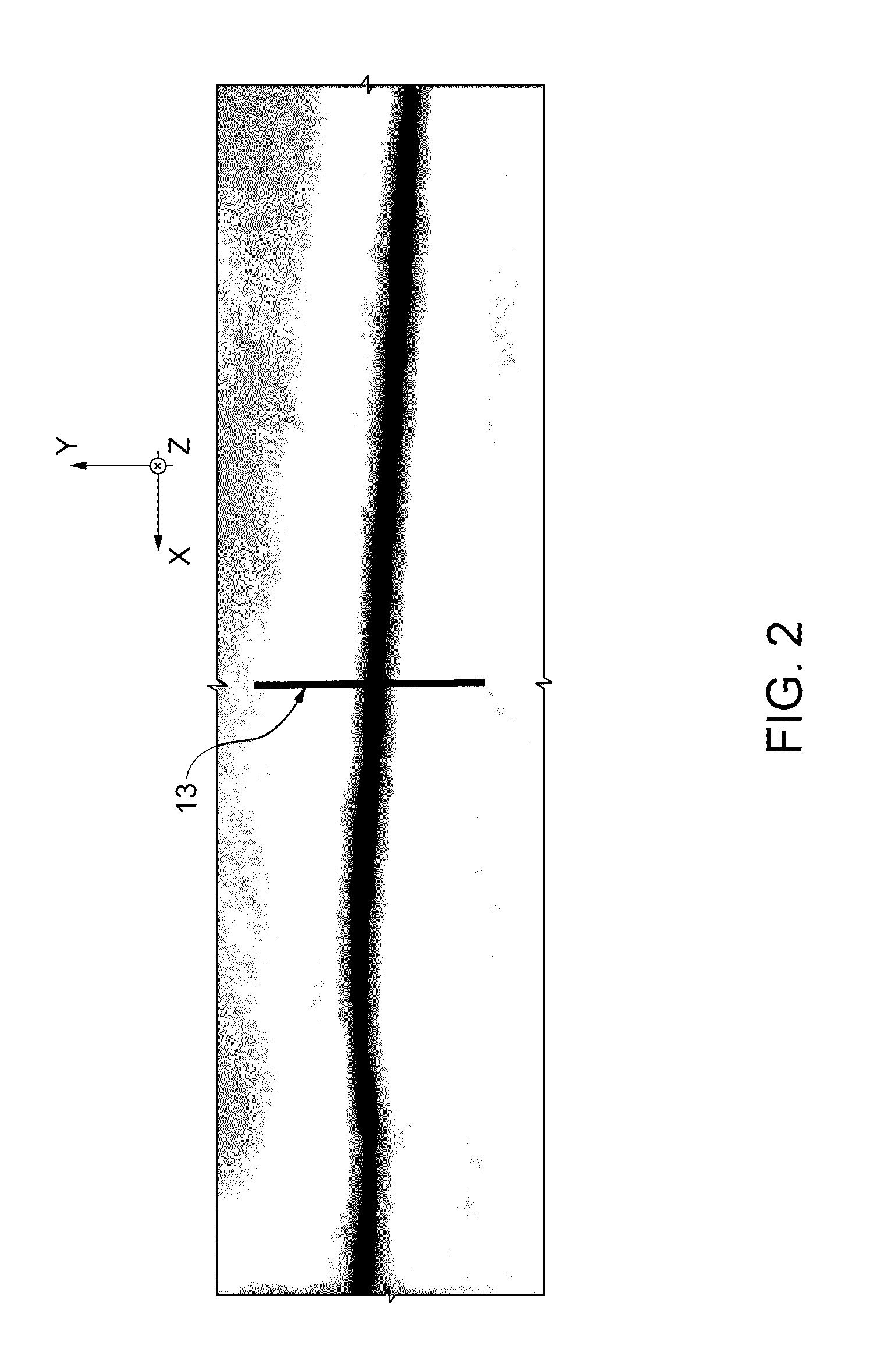
[0027]La present invention relates to the technical field of thermographic non-destructive inspection of a composite material structure, defined between a top surface and a bottom surface, to detect and measure at least a volumetric defect that extends from the top surface towards the bottom surface without necessarily reaching it. The above-mentioned volumetric defect is also known as a “resin pocket”, and has a significant spatial extension in three dimensions defined by Cartesian axes X (length), Y (width) and Z (depth).

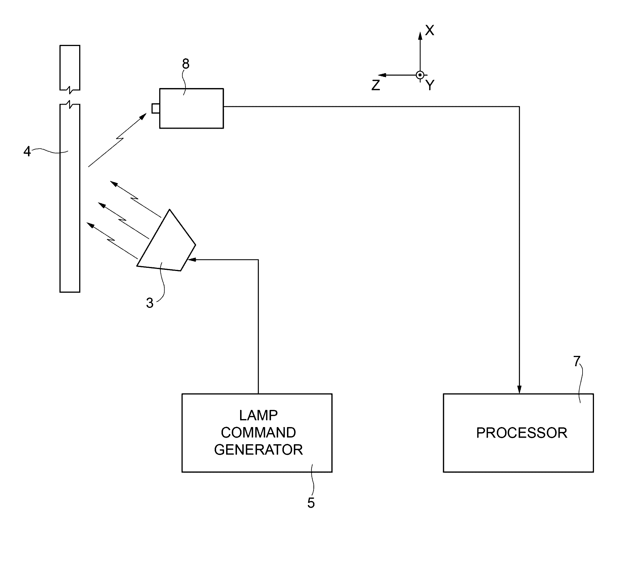
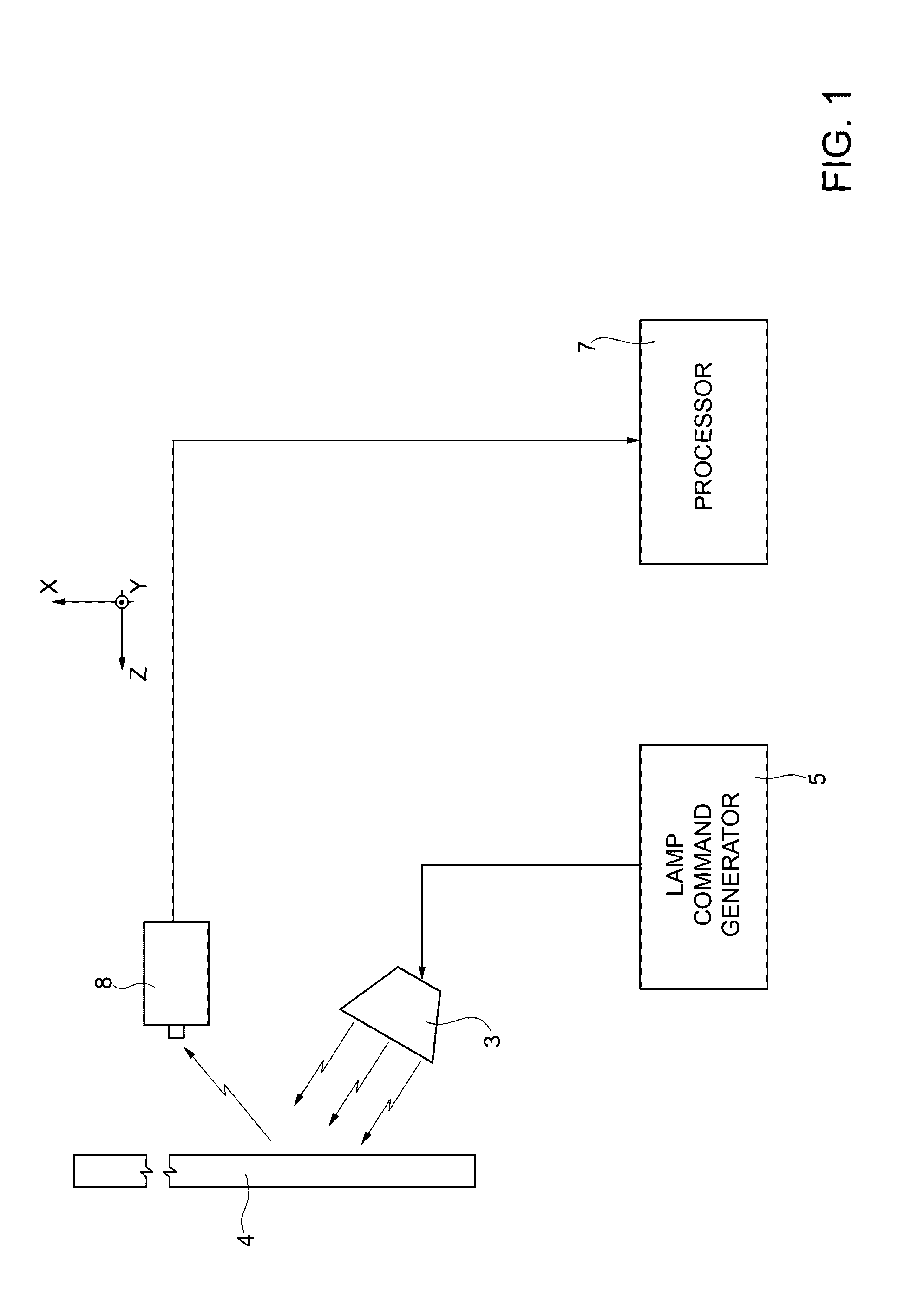
[0028]In this context, width and length identify the dimensions of the defect that extend along directions Y and X, respectively, these directions being mutually orthogonal but lying parallel to the incidence surface (KY plane) of the modulated thermal wave emitted by the halogen lamp(s) 3 onto the item 4 (see FIG. 1). The width along Y of the defect has a value less than the length along X. Instead, the depth of the defect along Z identifies an extension of the d...


PUM

PropertyMeasurementUnit
distanceaaaaaaaaaa
temperatureaaaaaaaaaa
dimensionaaaaaaaaaa

Abstract

A thermographic non-destructive inspection method of a structure, comprising the steps of: generating a modulated thermal wave in the direction of the structure; generating a temperature signal identifying a phase shift between the modulated thermal wave and a return thermal wave emitted from the structure; processing the temperature signal to obtain a first sub-signal related to the phase of the first harmonic of the temperature signal; identifying a first dimension of said defect as a function of the phase of the first harmonic of the temperature signal; calculating a first and a second intermediate parameter, ΔΦ1 for the first harmonic and ΔΦ2 for the third harmonic of the temperature signal, by calculating the difference, in degrees, between the phase value inside the zone with a defect and the phase value, absolute or mean of a plurality of points, of the undamaged zone close to the defect; and identifying a second dimension of the defect as a function of the first dimension and of the intermediate parameters ΔΦ1 and ΔΦ2.

Description

[0001]The present invention relates to a thermographic non-destructive inspection method and system for detecting and measuring defects of a volumetric type, such as, for example, resin pockets in composite material structures.BACKGROUND OF THE INVENTION[0002]As is known, during the manufacture of laminar composite material structures, for example in carbon, a resin matrix is used to keep the fibres in place and give shape to the manufactured composite article. In this context, the formation of undesired pockets, or accumulations, of resin that would compromise the stress resistance of the article manufactured in this manner are sometimes observed. The formation process of resin pockets is the following (other types of pocket originate in a similar manner): when layers of composite material deform (orthogonally to the lamination plane) during manufacture, empty spaces or anomalous pressure conditions may generate. In particular, during the polymerization phase, resin in the liquid p...

Claims


Application Information

Patent Timeline
Patent Type & Authority Applications(United States)
IPC IPC(8): G01N25/72G01B21/18G01J5/10
CPCG01N25/72G01J5/10G01J2005/0077G01J2005/0081G01B21/18G01M5/0033G01M99/002G01J5/48
Inventor MAIONE, GIACOMOINCARNATO, CIROCILIBERTO, ANTONIOGALIETTI, UMBERTOPALUMBO, DAVIDECERRONE, GIANPIERO
Owner LEONARDO SPA
Why Eureka
Try Eureka