
Method and device for detecting a deterioration state of a load bearing capacity in a suspension member arrangement for an elevator

a technology of load bearing capacity and suspension member, which is applied in the direction of elevators, instruments, transportation and packaging, etc., can solve the problems of increasing the potential for errors of the monitoring method, not being able to visually count broken wires, and significant sources of possible errors, etc., and achieves the effect of simple measuremen

Active Publication Date: 2017-02-02
INVENTIO AG
View PDF10 Cites 35 Cited by
  • Summary
  • Abstract
  • Description
  • Claims
  • Application Information

AI Technical Summary

Benefits of technology

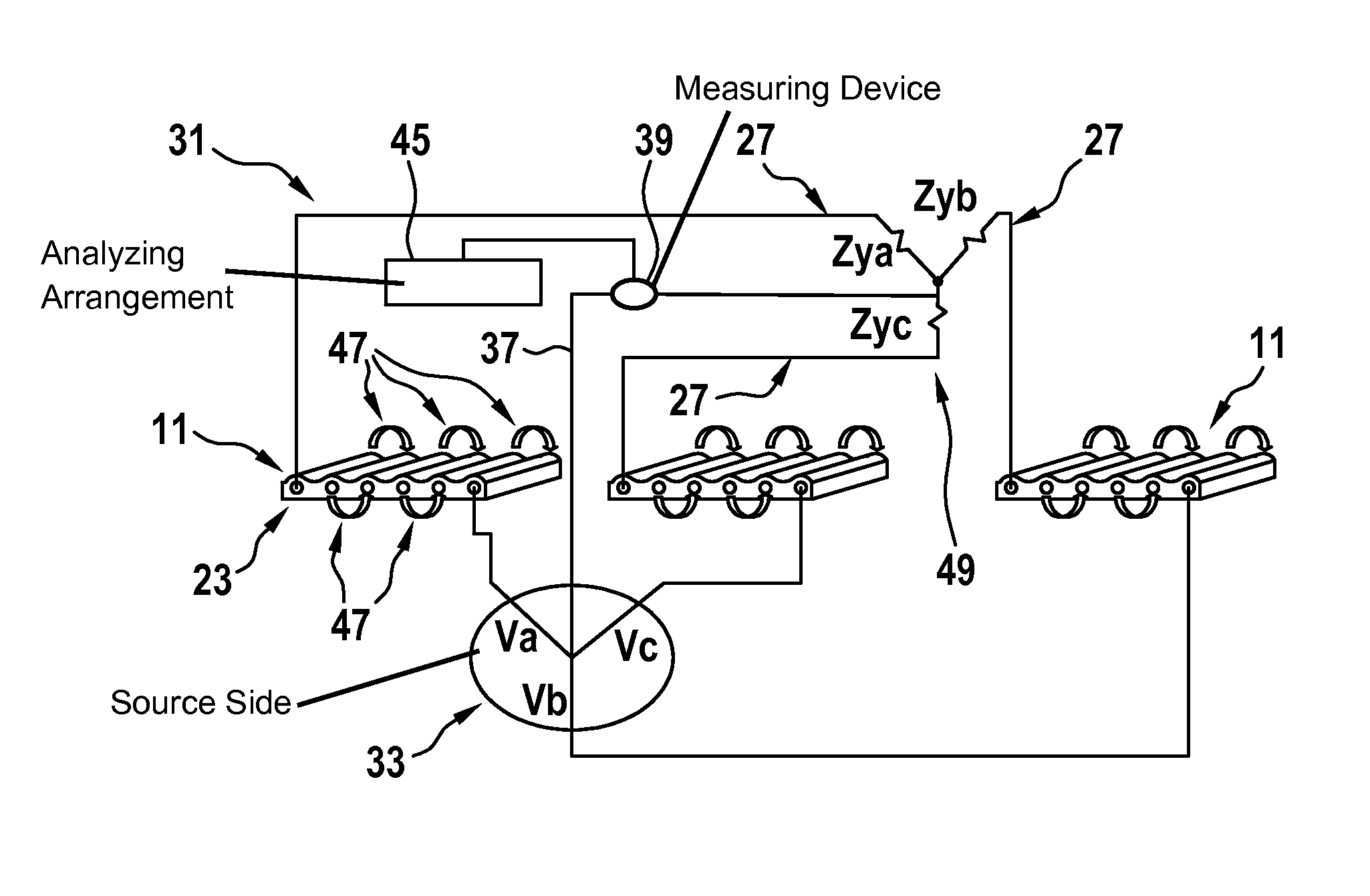
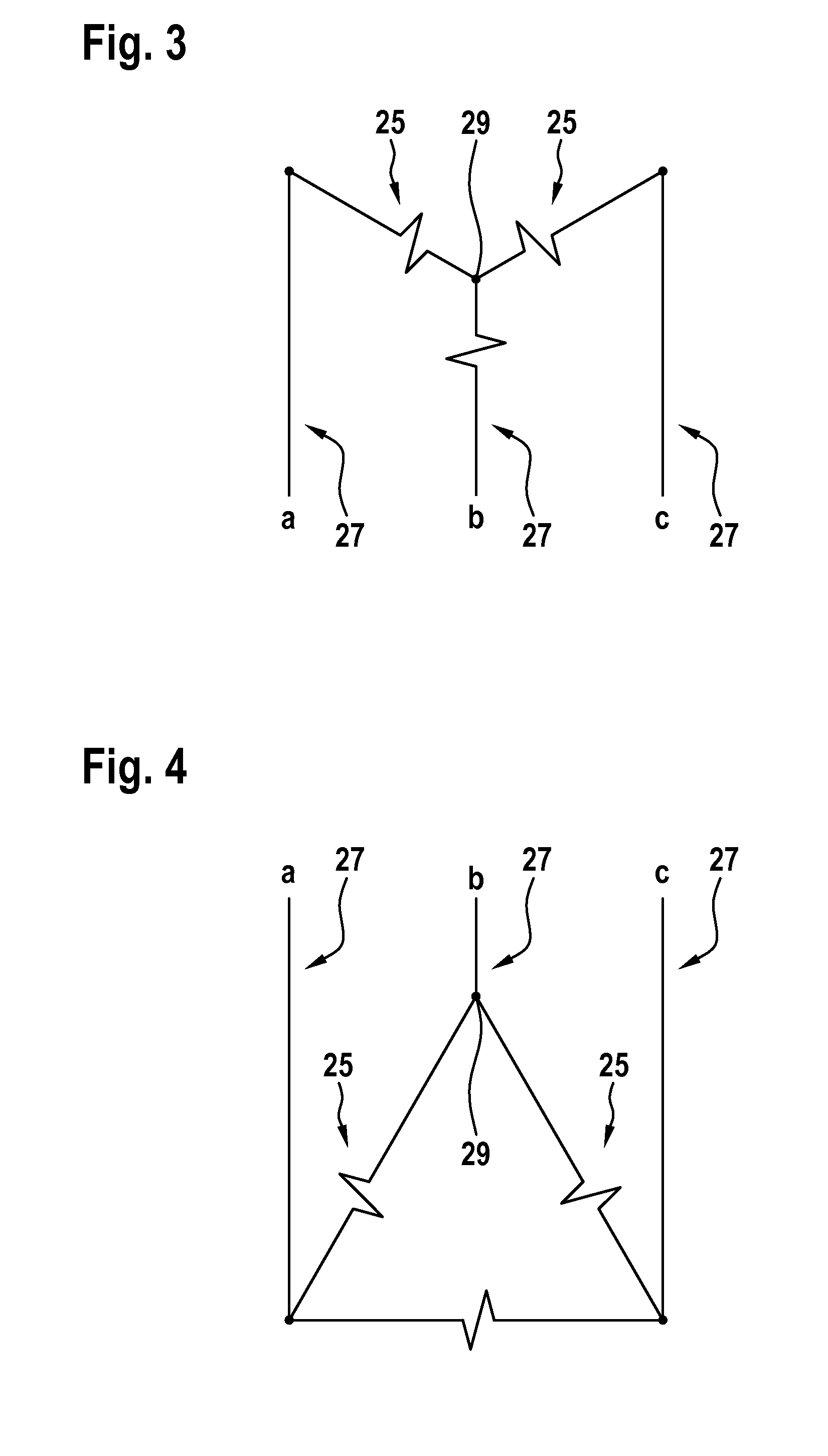
The present invention provides a method for measuring the electrical resistance / conductivity of cords used in elevator systems to ensure safe operation. The inventors found that measuring these characteristics is not necessary to obtain sufficient information about the suspension member arrangement. The invention suggests using a simple contactless measuring method based on induction, which allows for a quick and easy measurement without the need for a direct physical connection between the measuring device and the cords. The invention also suggests using a Wye-configuration for the multi-phase alternating current circuitry, which may enable the measurement of an electric indicator current to indicate any changes in the phase relationships. This may help to easily identify any deterioration in the suspension member arrangement. The phases of the multi-phase alternating current are supplied with an even phase offset from each other, which contributes to a balanced current distribution throughout the circuitry.

Problems solved by technology

For example, counting broken wires may be a tedious task periodically performed by persons maintaining the suspension members of an elevator and may be flawed by human error.
In cases where suspension members have an opaque coating on the metal cords or the metal cords are incorporated into a matrix material, it is generally not possible to visually count broken wires.
Where methods employ monitoring a change in electrical resistance or impedance of metal cords, the measurements are generally made across electrical connections to the steel cords and may introduce, by nature of such electrical connections, a significant source of possible errors due to for example very low electrical values of resistances being monitored.
Furthermore, over time, such electrical connections may deteriorate due to effects of e.g. oxidation and / or contamination and may increase a potential for errors by the monitoring method.
Additionally, such methods typically involve complex circuits necessary for measuring the very small changes in resistance or impedance and comparing them for example to target reference resistance values that may drift over time or due to effects of temperature.
Furthermore, some prior art approaches may require extensive correlation to map a change in resistance or impedance of the steel cords with changes in a strength and / or physical deterioration of the steel cord.
However, upon deterioration of one of the cords, the resistance Z1x created thereby in one of the lines changes and the entire multi-phase alternating current circuitry 31 comes into imbalance.
This may save work efforts and material costs.
Furthermore, such ohmic contact may otherwise frequently cause long-term problems such as corrosion, contact losses, etc.
In such configuration, altering electro-physical characteristics in one of the cords 23 may result in an imbalance in the multi-phase alternating current through the circuitry 31 such that a change in the indicator current may be measured.

Method used


Image

  • Method and device for detecting a deterioration state of a load bearing capacity in a suspension member arrangement for an elevator
  • Method and device for detecting a deterioration state of a load bearing capacity in a suspension member arrangement for an elevator
  • Method and device for detecting a deterioration state of a load bearing capacity in a suspension member arrangement for an elevator

Examples


Embodiment Construction

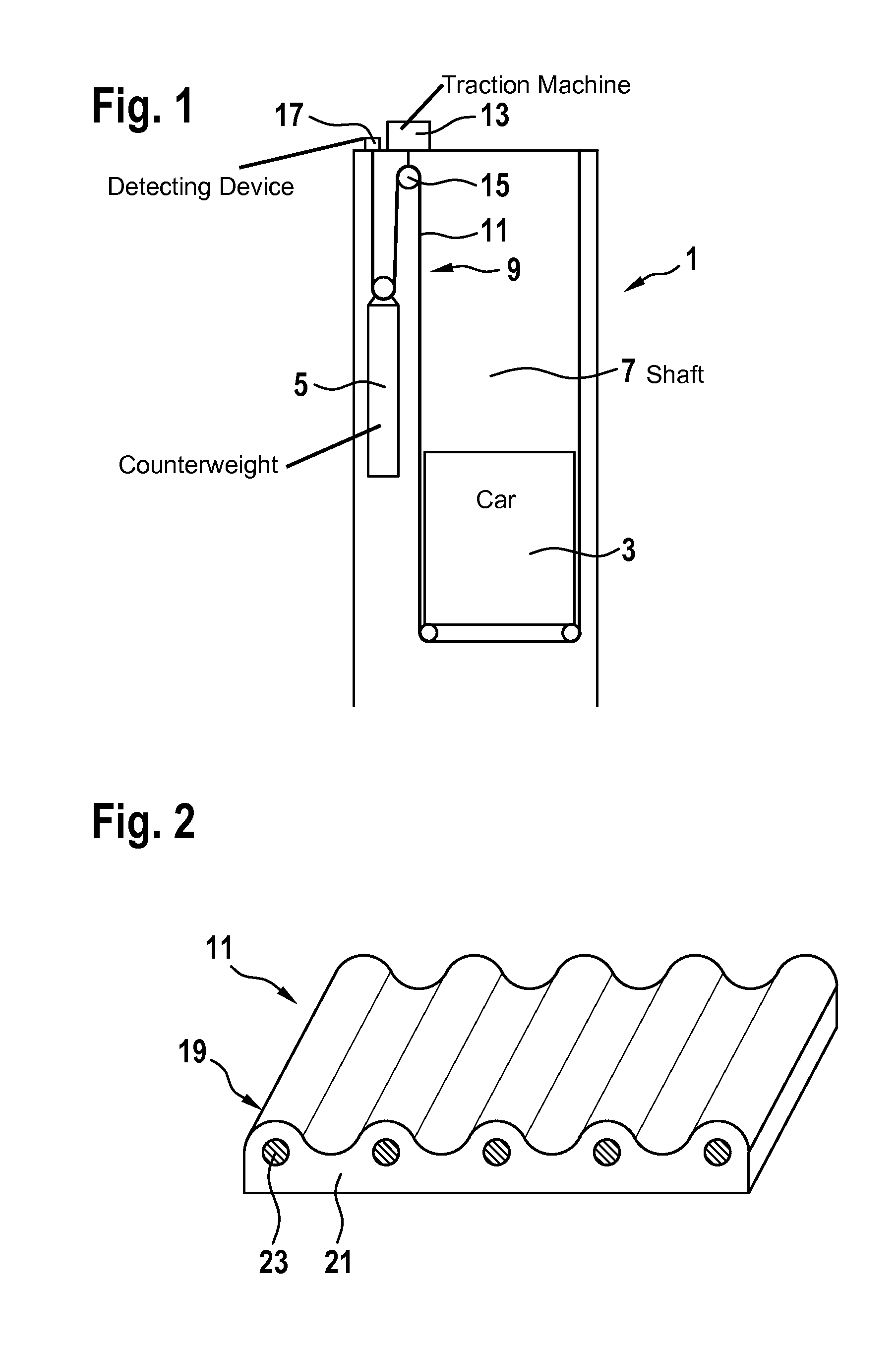
[0062]FIG. 1 shows an elevator 1 in which the method and / or device according to embodiments of the present invention may be implemented.

[0063]The elevator 1 comprises a car 3 and a counterweight 5 which may be displaced vertically within an elevator shaft 7. The car 3 and the counterweight 5 are suspended by a suspension member arrangement 9. This suspension member arrangement 9 comprises one or more suspension members 11. Such suspension members 11 may be for example ropes, belts, etc. In the arrangement shown in FIG. 1, end portions of the suspension members 11 are fixed to a supporting structure of the elevator 1 at a top of the elevator shaft 7. The suspension members 11 may be displaced using an elevator traction machine 13 driving a traction sheave 15. For example, at one end portion of the suspension member arrangement 9, a device 17 for detecting a deterioration state of a load bearing capacity in the suspension member arrangement 9 may be provided.

[0064]It may be noted that...


PUM


Abstract

A deterioration state of load bearing capacity in an elevator suspension member having a plurality of electrically conductive cords is detected by: providing a multi-phase alternating current circuitry including electrically conductive legs; applying at least one phase of a multi-phase alternating current to at least one of the cords electrically connected to one of the legs; applying at least another phase of the current to at least another cord and at least one resistor electrically connected to at least another leg; measuring an electric indicator current being at least one of a net sum of all phases of the current and an electric bypass current through a neutral wire being connected in parallel to the circuitry, wherein a peak current in each phase is shifted by a phase angle with respect to a peak current in another phase; and determining the deterioration state based on the measured indicator electric current.

Description

FIELD[0001]The present invention relates to a method and to a device for detecting a deterioration state of a load bearing capacity in a suspension member arrangement for an elevator.BACKGROUND[0002]Elevators typically comprise a car and, optionally, a counterweight which may be displaced for example within an elevator shaft to different levels in order to transport persons or items for example to various floors within a building. In a common type of elevator, the car and / or the counterweight are supported by a suspension member arrangement comprising one or more suspension members. A suspension member may be a member which may carry heavy loads in a tension direction and which may be bent in a direction transverse to the tension direction. For example, a suspension member may be a rope or a belt. Typically, suspension members comprise a plurality of cords. The cords may be made for example with a metal such as steel.[0003]During operation of the elevator, suspension members have to...

Claims


Application Information

Patent Timeline
Patent Type & Authority Applications(United States)
IPC IPC(8): B66B7/12
CPCB66B7/1223B66B7/1215G01R31/08D07B1/145B66B7/085B66B19/007G01R31/008B66B5/00G01R31/31723B66B5/0018D07B2501/2007D10B2401/16G01R31/081B66B7/062G01M5/0033G01M5/0091G01N27/20
Inventor ROBIBERO, VINCENT
Owner INVENTIO AG
Learn More