Power generation system

a power generation system and power generation technology, applied in the direction of steam generation using solar heat, machines/engines, lighting and heating apparatus, etc., can solve the problems of increasing the difficulty of popularizing the power generation system, power plants require large investment, etc., and achieve the economic and environmental benefits of the power plant, the effect of enhancing the installed capacity of the combined power plan

Active Publication Date: 2017-02-02
WUHAN KAIDI ENG TECH RES INST CO LTD
View PDF11 Cites 10 Cited by
  • Summary
  • Abstract
  • Description
  • Claims
  • Application Information

AI Technical Summary

Benefits of technology

[0016]3. The heat source of the BIGCC system is utilized, the configuration of the photothermal power generation is simplified, the light field is not configured with auxiliary heating device or turbines or electric generator that adopts the photothermal steam and the exhaust heat steam of the BIGCC, so that the investment into the photothermal power generation device is reduced.
[0018]5. By configuration of the heat storage and the system integration, the intermittence and instability of the solar energy supply are effectively solved.
[0019]6. Based on the clean and effective system platform of the BIGCC, the efficiency of the photothermal power generation is improved. The steam turbine and the auxiliary heating device for the photothermal power generation and the system investment thereof are saved, the investment production of the photothermal power generation are reduced. The biomass resource in the proximity of the power plant is utilized, thus making ISCC independent from the natural gas resource and the supply network. In addition, the light and the heat are effectively complemented, the installed capacity of the combined power plant, and the economic benefit and the environmental benefit of the combined power plant are improved.
[0021]8. The replenishment of the light and the heat is adopted, the installed capacity of the combined power plant is enlarged, and the economic and environmental benefits of the power plant are improved.

Problems solved by technology

The power plants require large investment, and is highly dependent on the conventional fossil energy which is nonrenewable.
This increases the difficulty to popularize the power generation systems.

Method used


Image

  • Power generation system
  • Power generation system
  • Power generation system

Examples


Embodiment Construction

[0027]For further illustrating the invention, experiments detailing a power generation system are described below. It should be noted that the following examples are intended to describe and not to limit the invention.

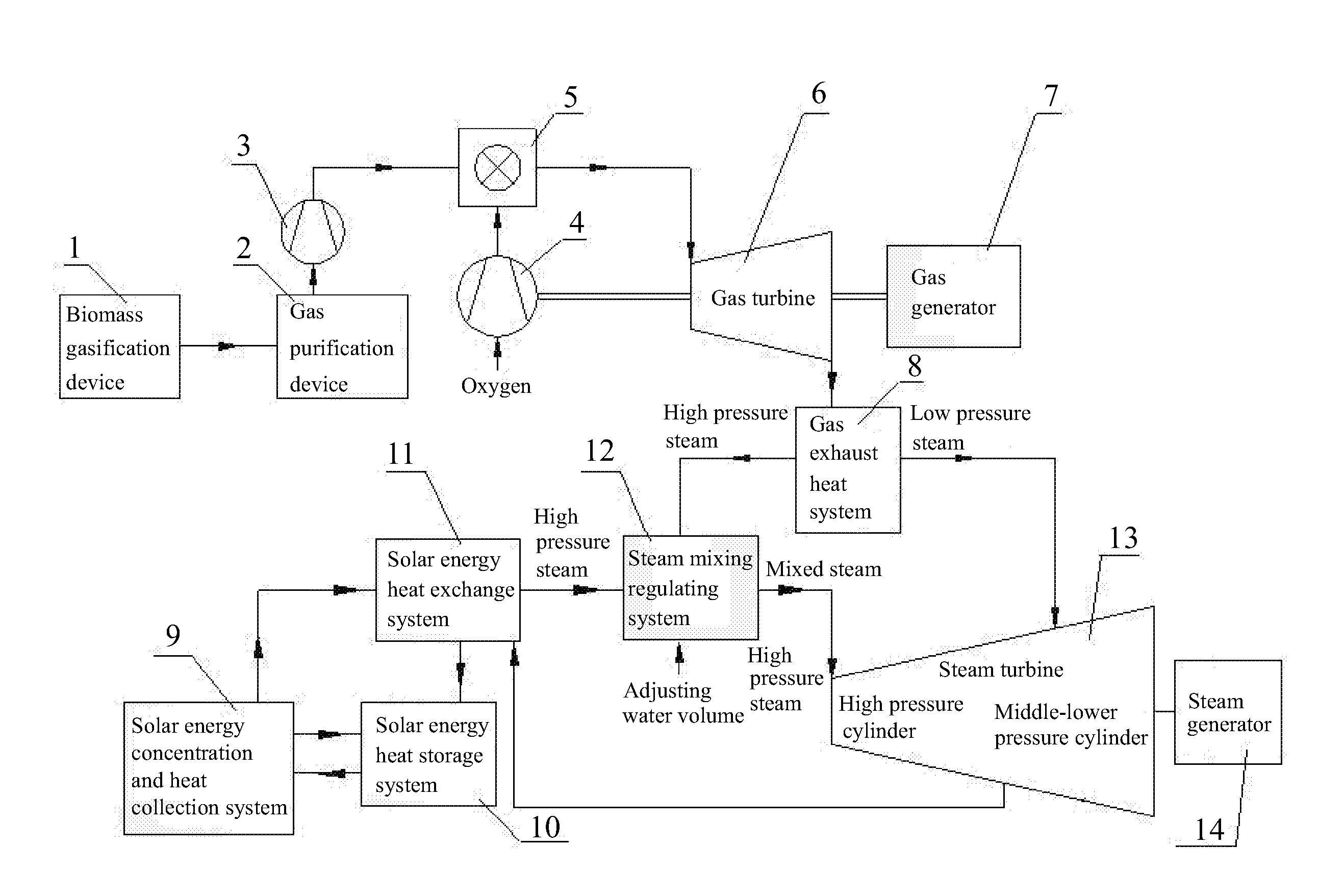
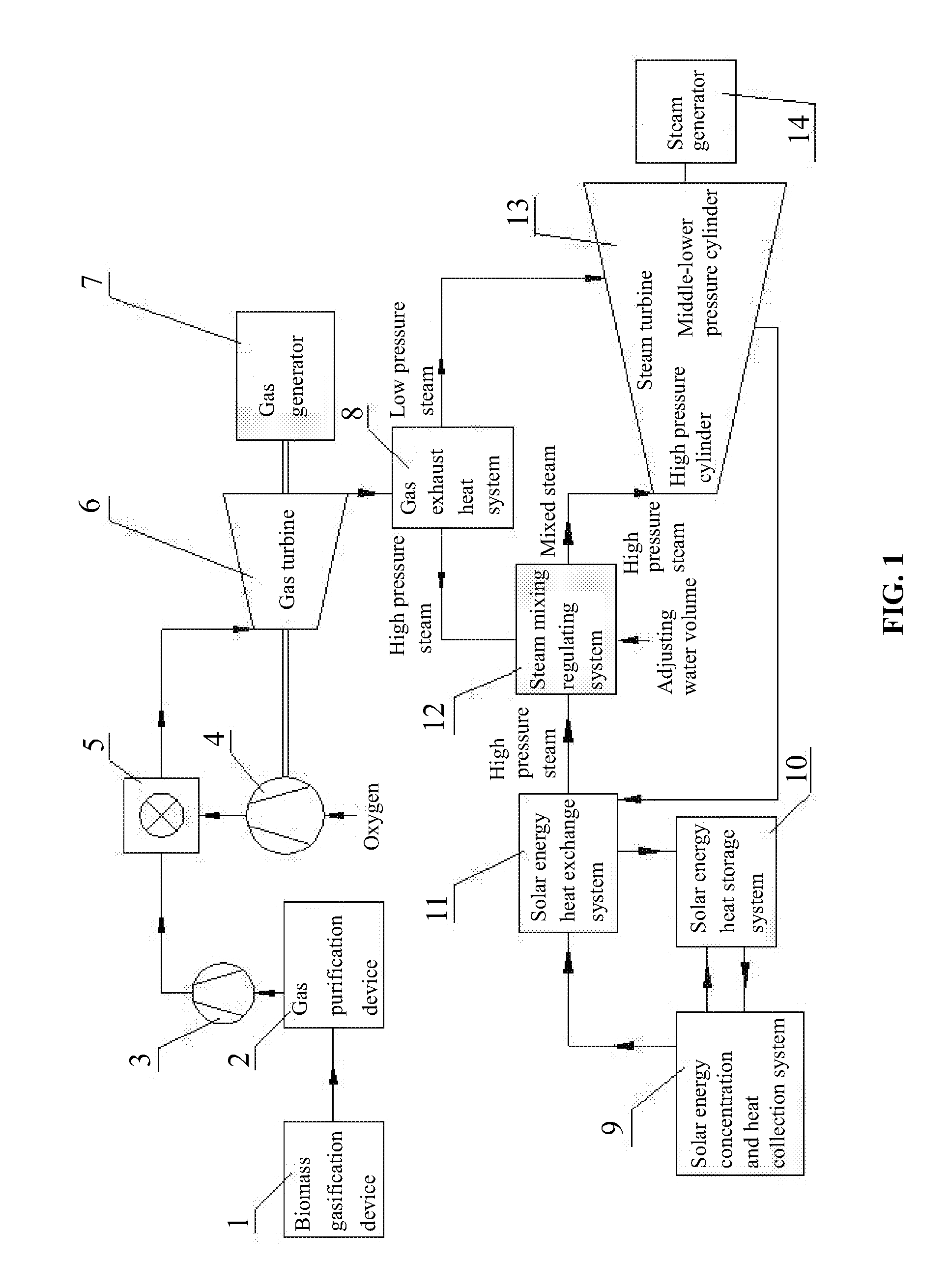
[0028]Combined with a Rankine cycle as a bottom cycle of BIGCC and the characteristics of the operation of the sliding-parameters of the steam turbine, a system of the steam mixing regulating system is established. A through type solar energy photothermal steam and the afterheat steam of the BIGCC are mixed, and a temperature of a resulting mixed steam is regulated, then the mixed steam is utilized as a primary steam and sent to a steam turbine to do work while expanding, thus driving the generator for power generation and realizing power generation of both the solar energy photothermal steam and the afterheat steam of the BIGCC.

[0029]As shown in FIG. 1, a power generation system integrated with solar energy and BIGCC, the system comprises: a solar energy concentration...


PUM


Abstract

A power generation system, including: a solar energy concentration system, a biomass gasification device, a gas-powered generator, a steam turbine, a steam-powered generator. The solar energy concentration system is connected to a solar energy heat exchange system. The biomass gasification device is connected to the gas-powered generator. The gas outlet of the gas turbine is connected to the gas exhaust heat system. The second steam outlet of the gas exhaust heat system is connected to the second and the third cylinders of the steam turbine. The first steam outlet of the gas exhaust heat system and the steam outlet of the solar energy heat exchange system are connected to a steam mixing regulating system. The mixed steam outlet of the steam mixing regulating system is connected to the first cylinder of the steam turbine.

Description

CROSS-REFERENCE TO RELATED APPLICATIONS[0001]This application is a continuation-in-part of International Patent Application No. PCT / CN2015 / 072397 with an international filing date of Feb. 6, 2015, designating the United States, now pending, and further claims priority benefits to Chinese Patent Application No. 201410144008.5 filed Apr. 11, 2014. The contents of all of the aforementioned applications, including any intervening amendments thereto, are incorporated herein by reference. Inquiries from the public to applicants or assignees concerning this document or the related applications should be directed to: Matthias Scholl P.C., Attn.: Dr. Matthias Scholl Esq., 245 First Street, 18th Floor, Cambridge, Mass. 02142.BACKGROUND OF THE INVENTION[0002]Field of the Invention[0003]The invention relates to a power generation system.[0004]Description of the Related Art[0005]Existing power generation systems combining solar energy and natural gas impose high requirements on the construction ...

Claims


Application Information

Patent Timeline
Patent Type & Authority Applications(United States)
IPC IPC(8): F02C3/28H02K7/18F01K3/18F01D15/10F02C3/04F24S90/00
CPCF02C3/28F01D15/10F02C3/04F05D2220/76H02K7/1823F05D2210/12F01K3/18F01K7/18F22B1/006F22B1/1815F03G6/02Y02E10/46Y02E20/14Y02E20/18Y02E50/10Y02T10/7072F01K27/00F02C6/00
Inventor CHEN, YILONGZHANG, YANFENGTANG, HONGMINGLIU, WENYAN
Owner WUHAN KAIDI ENG TECH RES INST CO LTD
Why Eureka
Try Eureka