
Light valve panel and liquid crystal display using the same

a technology of liquid crystal display and light valve panel, which is applied in the direction of non-linear optics, static indicating devices, instruments, etc., can solve the problem that the liquid crystal display is not good in displaying a dark imag

Active Publication Date: 2017-02-02
LG DISPLAY CO LTD
View PDF4 Cites 19 Cited by
  • Summary
  • Abstract
  • Description
  • Claims
  • Application Information

AI Technical Summary

Benefits of technology

The present invention is about a light valve panel that can improve the contrast ratio of a display by controlling the amount of light incident on each pixel. This panel can reduce luminance and color distortion at a side viewing angle and prevent a bright line phenomenon. The invention also includes a liquid crystal display with a display panel, backlight unit, and light valve panel that adjusts the amount of light from the backlight unit based on the input image. The light valve panel has blocks that are divided into segment electrodes connected through a resistance pattern, which enables a voltage distribution to the segment electrodes of each block.

Problems solved by technology

A liquid crystal display is not good in displaying a dark image due to the backlight.

Method used


Image

  • Light valve panel and liquid crystal display using the same
  • Light valve panel and liquid crystal display using the same
  • Light valve panel and liquid crystal display using the same

Examples


Embodiment Construction

[0027]Reference will now be made in example embodiments of the invention, of which are illustrated in the accompanying drawings. Wherever possible, the same reference numbers will be used throughout the drawings to refer to the same or like parts. It will be paid attention that detailed description of known arts will be omitted.

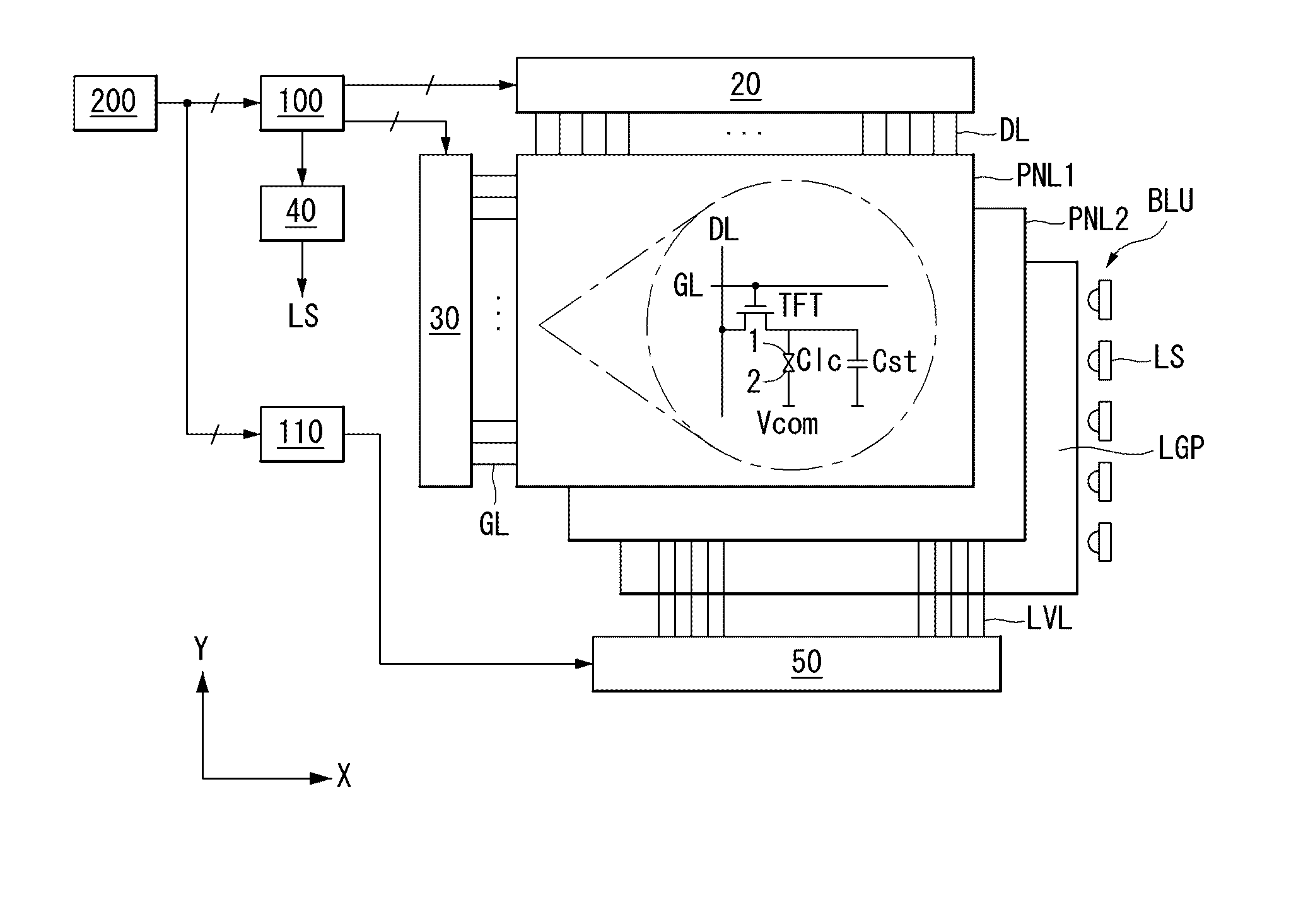
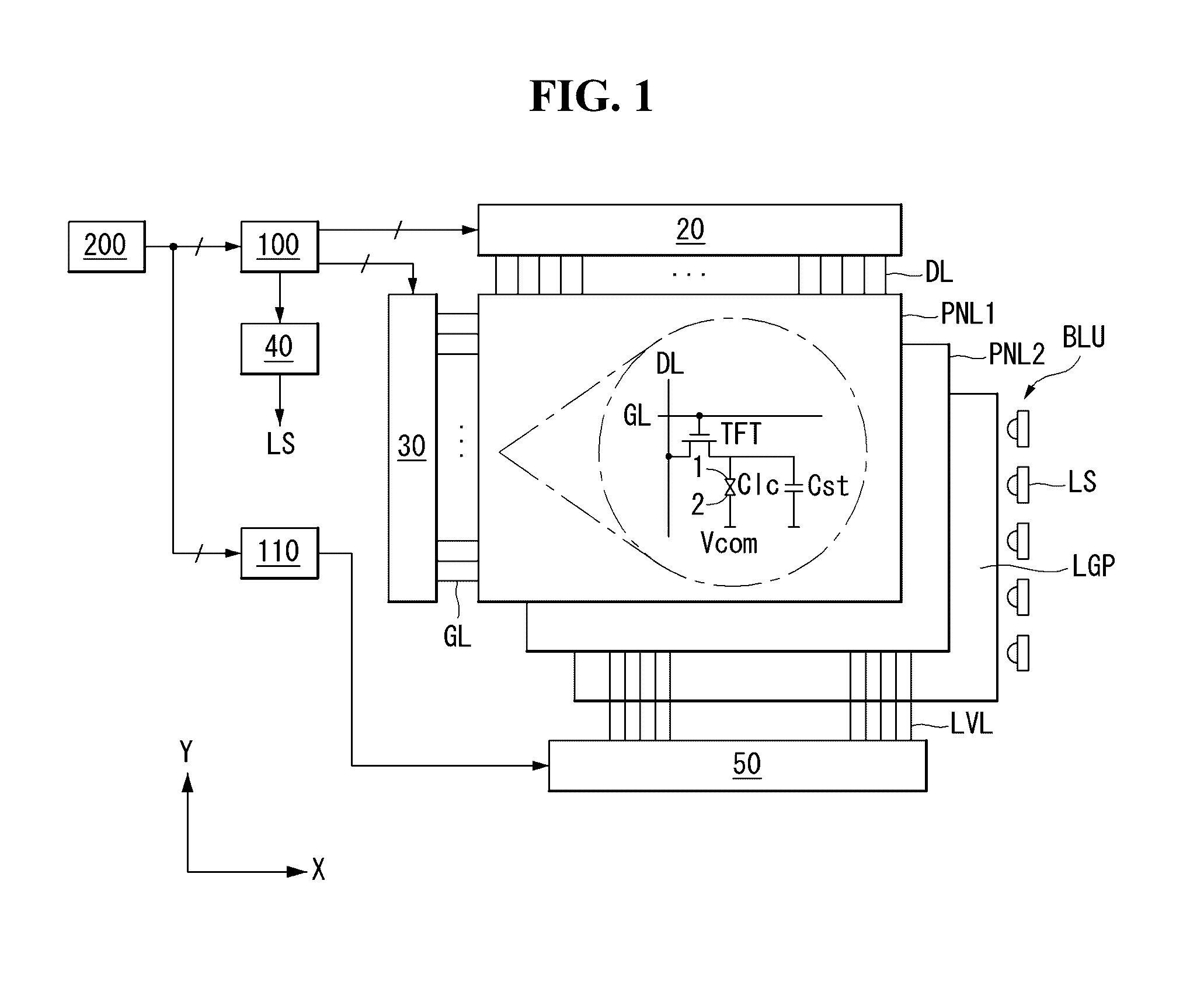
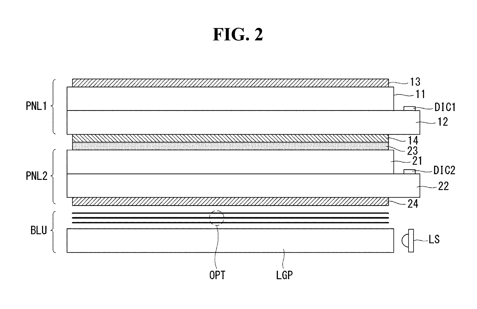
[0028]Referring to FIGS. 1 and 2, a liquid crystal display according to an embodiment of the invention includes a display panel PNL1 including a pixel array, a backlight unit BLU irradiating light onto the display panel PNL1, a light valve panel PNL2 disposed between the display panel PNL1 and the backlight unit BLU, a first panel driving circuit, a second panel driving circuit, and a backlight driving circuit 40.

[0029]The display panel PNL1 includes an upper plate and a lower plate, that are positioned opposite each other with a liquid crystal layer interposed therebetween. The pixel array of the display panel PNL1 includes pixels arranged in a matrix form b...


PUM

PropertyMeasurementUnit
angleaaaaaaaaaa
viewing angleaaaaaaaaaa
voltageaaaaaaaaaa

Abstract

A light valve panel and a liquid crystal display using the same are discussed. The light valve panel according to an embodiment includes a transparent electrode layer having a plurality of blocks supplied with a voltage through data input lines. The transparent electrode layer has a low resistance or has a high resistance. When a transparent electrode layer has low resistance, each block is divided into a plurality of segment electrodes connected through a resistance pattern. A voltage is distributed to the plurality of segment electrodes of each block based on the resistance pattern. When a transparent electrode layer has high resistance, the voltage distribution in each block is based on a resistance difference that varies based on a distance between voltage feeding positions.

Description

[0001]This application claims the priority benefit of Korean Patent Application No. 10-2015-0107596 filed on Jul. 29, 2015, the entire contents of which is incorporated herein by reference for all purposes as if fully set forth herein.BACKGROUND OF THE INVENTION[0002]Field of the Invention[0003]The present disclosure relates to a liquid crystal display that includes controlling an amount of light incident on a display panel based on a luminance distribution of an input image.[0004]Discussion of the Related Art[0005]Various flat panel displays, such as a liquid crystal display (LCD), a plasma display panel (PDP), an organic light emitting diode (OLED) display, and an electrophoresis display (EPD), have been developed. A liquid crystal display displays an image by controlling an electric field applied to liquid crystal molecules based on a data voltage and adjusting a light transmittance of pixels. An active matrix liquid crystal display includes a thin film transistor (TFT) in each p...

Claims


Application Information

Patent Timeline
Patent Type & Authority Applications(United States)
IPC IPC(8): G09G3/34G09G3/36G02F1/1335G02F1/1362G02F1/1368G09G3/20G02F1/1343
CPCG09G3/3406G02F2201/121G09G3/3688G02F1/134309G02F1/136286G02F1/1368G02F1/13439G02F1/133512G02F1/133528G09G2320/0242G09G2320/0233G09G2300/0426G09G2310/08G09G2320/0276G09G2320/0626G02F2201/123G09G3/2007G09G3/342G09G3/3637G09G3/364G09G3/3648G09G2300/023
Inventor YOO, OOKSANGLEE, JUYOUNGNAM, SANGJINYOO, SEUNGJIN
Owner LG DISPLAY CO LTD
Learn More