Thermal engine with energy modulation mechanism

Inactive Publication Date: 2017-02-09
WEI HUANG
View PDF0 Cites 0 Cited by
  • Summary
  • Abstract
  • Description
  • Claims
  • Application Information

AI Technical Summary

Benefits of technology

This invention aims to address the issues of previous thermal engines by providing a mechanism to regulate gas expansion and compression. It also offers an effective heat exchange system for separating oxygen from ambient air and using pure oxygen combustion for fuel. This helps to reduce emissions. Additionally, the engine can store excessive heat energy into low-density energy sources, such as compressed air or electrical energy, for later use. The energy storage capacity of this engine is high, providing a high-density energy source for fuel.

Problems solved by technology

Conventional thermal engine designs do not have careful consideration on the characteristics of thermal energy behavior, especially its energy distribution during expansion and compression.
Another existing issue with thermal engines is how to convert reciprocation motion of the pistons into rotary motion efficiently.
Though, crankshaft and other conventional solutions are inefficient.
The problem multiplies as compression of gaseous working fluid also relies on crankshaft, which will further draw more energy from the expansion.
Therefore, as the result, the compression needs more energy from the expansion because of crankshaft inefficiency.

Method used


Image

  • Thermal engine with energy modulation mechanism
  • Thermal engine with energy modulation mechanism
  • Thermal engine with energy modulation mechanism

Examples


Embodiment Construction

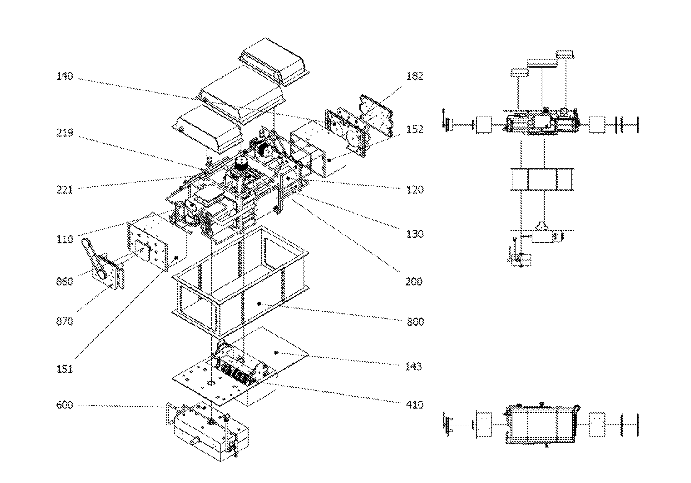
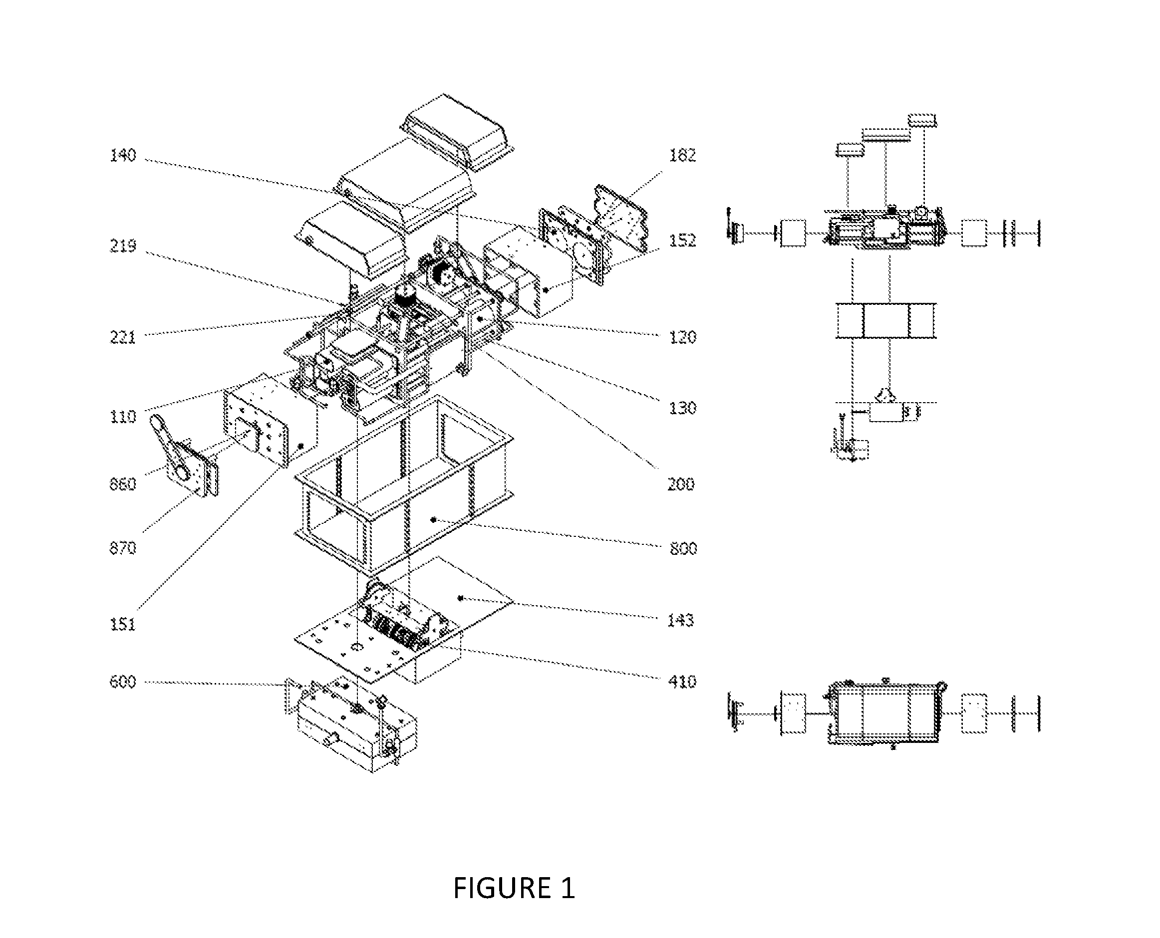
[0040]FIG. 1 shows a perspective view of the apparatus and its components in accordance with the mechanical structure and arrangement. The apparatus consists of a single or multiple stage compressor 110. The compressor 110 is cylindrical and has a thin wall of rust-resistant metal chambers where gas will be volumetrically reduced by pistons. When the gas is volumetrically reduced thermal energy is stored for each cycle of compression. In order to achieve optimum energy efficiency, the compressor 110 includes at least one pair of cylinders, each having a piston and a rod. The compressor 110 may also be comprised of a pair of compression units, each unit including a plurality of compressors for multi-staged compression. Although several configurations for the compressor 110 can be used, the embodiment described below is a two-staged compressor having two cylinders for the first stage and one cylinder for the second stage.

[0041]The compressor 110 is connected to a heat expander 120 and...


PUM


Abstract

Disclosed herein is an apparatus for extracting thermal energy from thermal expansion of a working medium in the apparatus. The apparatus includes a thermal expander, a compressor for compressing the working medium after the expansion, and a force modulation unit connecting the thermal expander to the compressor. The force modulation unit consists of two conversion gears that are connected by a lever system. The lever system can be dynamically controlled so that the non-constant force from thermal expansion is modulated into a substantially constant output force of the apparatus.

Description

TECHNICAL FIELD[0001]The present invention relates to thermal engines. More particularly, the invention relates to a thermal engine that converts thermal energy into mechanical energy, having an energy modulation mechanism to utilize thermal energy more efficiently.BACKGROUND ART[0002]Conventional thermal engine designs do not have careful consideration on the characteristics of thermal energy behavior, especially its energy distribution during expansion and compression. Although it has been observed that gas expansion energy is a non-constant force, the non-constant energy is used in all prior art thermal engines.[0003]Another existing issue with thermal engines is how to convert reciprocation motion of the pistons into rotary motion efficiently. A crankshaft is conventionally used to convert reciprocation motion into rotary motion. Though, crankshaft and other conventional solutions are inefficient. Following equation illustrates the relationship of piston head instantaneous force...

Claims


Application Information

Patent Timeline
IPC IPC(8): F02G1/05F02G1/055
CPCF02G1/05F02G2270/90F02G1/055F01B23/08F01B9/047F02G1/00F02G1/053F02G1/04
Inventor HUANG, DA WEI
Owner WEI HUANG
Why Eureka
Try Eureka