Method And Device For Measuring Fluid Properties Using An Electromechanical Resonator

a technology of electromechanical resonators and fluid properties, which is applied in the field of electromechanical resonators to measure fluid properties, can solve the problems of high cost and time consumption of measurement, inability to accurately reverse changes, and inability to accurately capture samples at a well, so as to reduce the response time

Active Publication Date: 2017-02-09
SAUDI ARABIAN OIL CO
View PDF8 Cites 19 Cited by
  • Summary
  • Abstract
  • Description
  • Claims
  • Application Information

AI Technical Summary

Benefits of technology

[0016]In a further embodiment, oleophobic or hydrophobic coatings such as pyrelene or fluorinated compounds are used to preferentially measure a particular phase (brine or oil) in a multiphase flow. In one embodiment, an omniphobic coating or super-repellant surface is applied to the electromechanical resonator to reduce the response time in sensing a change in fluid type between hydrocarbons and brine.

Problems solved by technology

However, when hydrocarbon liquids from the reservoir are brought to surface temperature and pressure (e.g., as they travel up a well) dissolved gas is released and asphaltenes may precipitate.
These changes can be difficult to accurately reverse in the laboratory, so that the viscosity measured in the laboratory may be different from the viscosity that the fluids had in the reservoir, even if the laboratory measurement is made at reservoir temperature and pressure.
Furthermore, the process of acquiring samples at a well, transporting them to a laboratory, and making measurements there is costly and time consuming.
In addition, the need to transport samples to a lab to acquire fluid properties data prevents these data from being used in real time to respond to changing conditions at the well.
However, due to the irreversible changes that can occur in fluids as they are brought to the surface as well as uncertainty around exactly where certain conditions of pressure and temperature will be met in the actual well, these inferences may be inaccurate.
The flow regime can significantly impact the effectiveness and durability of downhole equipment, such as artificial lift systems.
In some flow regimes, the different phases move at different velocities, which can lead to inaccurate measurements.
Small device size is also necessary due to limited space inside wells particularly in a scenario where permanent or tetherless sensing is desired while not significantly interfering with hydrocarbon production.

Method used


Image

  • Method And Device For Measuring Fluid Properties Using An Electromechanical Resonator
  • Method And Device For Measuring Fluid Properties Using An Electromechanical Resonator
  • Method And Device For Measuring Fluid Properties Using An Electromechanical Resonator

Examples


Embodiment Construction

[0033]According to a broad aspect of the present invention, the inventors recognized that a small, fast, and accurate sensor capable of measuring viscosity and density and mounted on a platform which enabled it to obtain measurements at various depths along a producing well can, for example, be used to 1) map the PVT characteristics of downhole fluids and identify the locations where the dew point, bubble point, and / or other important state changes and transitions in the fluid properties occur along the wellbore, 2) map the PVT characteristics of a dispersed fluid-fluid (emulsion), solid-fluid (suspension), gas-fluid (foam) system through rapid measurement of changes in density and viscosity 3) determine more accurately the true viscosity and density of the reservoir fluids at reservoir conditions, and 4) determine separate phase densities and viscosities and a time series of the instantaneous phase present at the sensor in a multi-phase flow, from which the flow regime, the shapes ...


PUM


Abstract

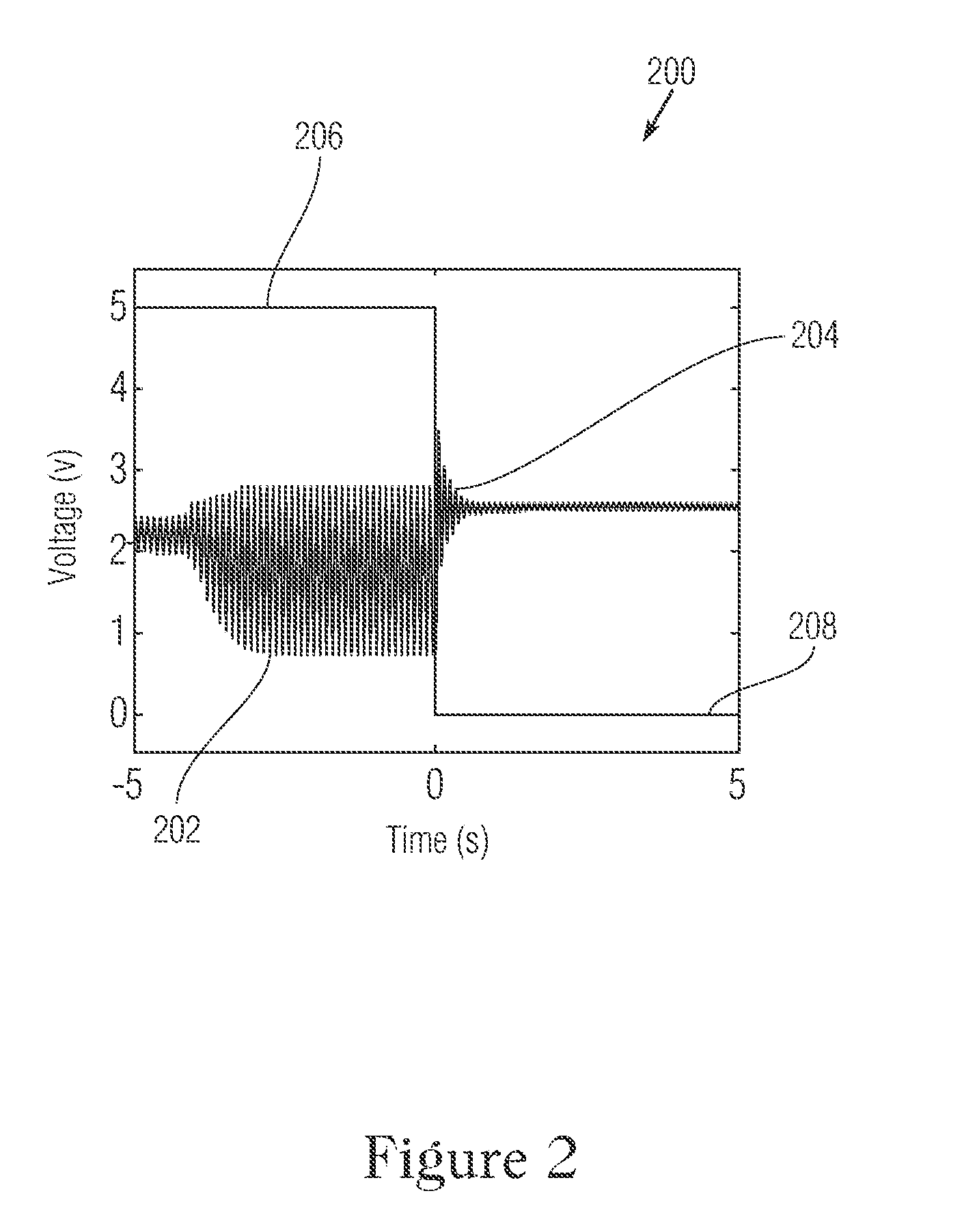
A method and device are described for making in situ measurements of the density and viscosity of downhole fluids at subterranean wells. An oscillator circuit is deployed in the well comprising an amplifier, a feedback loop, and an electromechanical resonator. The electromechanical resonator is a component in the feedback loop of the oscillator circuit, and has a resonance mode that determines the frequency of the oscillator circuit. The electromechanical resonator is also in contact with the fluid such that the density and viscosity of the fluid influence the resonant frequency and damping of the resonator. The frequency of the oscillator is measured by a microcontroller. In one embodiment, the oscillator circuit periodically stops driving the electromechanical resonator such that the oscillation decays and the rate of decay is also measured by the microcontroller. The density and viscosity of the fluid are determined from the frequency and rate of decay of the oscillation. This measurement technique provides a faster response time to fluid changes than is possible with conventional measurement methods, and the fast response time opens up new applications for downhole viscosity and density measurements, including determining PVT characteristics, phase diagrams, and flow rates.

Description

CROSS-REFERENCE TO RELATED APPLICATION[0001]The present invention claims priority to U.S. patent application Ser. No. 62 / 202,512, filed Aug. 7, 2015, which is hereby incorporated by reference in its entirety.FIELD OF THE INVENTION[0002]The present invention generally relates to the field of petroleum engineering, and more particularly to a method and device for obtaining in situ measurements at a subterranean well of the viscosity and density of downhole fluids.BACKGROUND OF THE INVENTION[0003]A multiplicity of hydrocarbons, brines, other liquids and gases and supercritical fluids, slurries, foams and emulsions are produced from, found in, used in the construction of, or injected into subterranean wells. These fluids will be known collectively as downhole fluids. Knowledge of the physical properties of these fluids, such as their density and viscosity, is critical to the drilling, completion, operation, and abandonment of wells. These wells may be used for recovering hydrocarbons fr...

Claims


Application Information

Patent Timeline
Patent Type & Authority Applications(United States)
IPC IPC(8): G01V1/50E21B49/08
CPCG01V1/50E21B49/087E21B2049/085G01N2009/006G01N11/16G01N9/002E21B49/08E21B49/0875
Inventor GONZALEZ, MIGUELDEFFENBAUGH, MAXSEREN, HUSEYINCSUTAK, SEBASTIAN
Owner SAUDI ARABIAN OIL CO
Why Eureka
Try Eureka