Peripheral field-of-view illumination system for a head mounted display

a technology of peripheral field of view and illumination system, which is applied in the field of virtual reality systems, can solve the problems of more expensive displays, and achieve the effects of simplifying the geometry and optics of the system, cost and sourcing advantages, and low cos

Active Publication Date: 2017-02-09
KAYA DYNAMICS LLC
View PDF7 Cites 8 Cited by
  • Summary
  • Abstract
  • Description
  • Claims
  • Application Information

AI Technical Summary

Benefits of technology

[0012]One or more embodiments include a left display and a right display, each located in front of the respective eye of the user. In one or more embodiments, the left display and right display may be substantially flat. Use of flat or substantially flat displays may provide cost and sourcing advantages since flat displays are readily available and can be manufactured at low cost. In one or more embodiments the left display and right display may be curved or formed from multiple sections angled with respect to one another; while curved displays may be more expensive in some cases, they may also simplify the geometry and optics of the system. Embodiments may use displays of any size or shape, along with one or more lenses to potentially increase the field of view.
[0013]In one or more embodiments, the left display and right display may be angled with respect to one another, rather than being parallel. For example, the angle between a plane tangent to the left display and a plane tangent to the right display may be less than 180 degrees, when measured from the side near the eyes of the user. This configuration may bring the left edge of the left display closer to the user's left eye, increasing the horizontal field of view perceived by the user. Similarly, this configuration may bring the right edge of the right display closer to the user's right eye, increasing the horizontal field of view perceived by the user.
[0014]One or more embodiments may include one or more lenses between the displays and the user's eyes. These lenses may for example form images of the displays that extends across a wider field of view than the displays themselves without the lenses. The lens or lenses may therefore increase the apparent field of view of the system. In one or more embodiments some or all of the pixels of the left and right displays may be substantially in focus when viewed through the lens or lenses. In one or more embodiment some or all of the pixels of the left and right displays may be out of focus to create diffuse images in certain portions of the field of view, for example at the periphery.

Problems solved by technology

In one or more embodiments the left display and right display may be curved or formed from multiple sections angled with respect to one another; while curved displays may be more expensive in some cases, they may also simplify the geometry and optics of the system.

Method used


Image

  • Peripheral field-of-view illumination system for a head mounted display
  • Peripheral field-of-view illumination system for a head mounted display
  • Peripheral field-of-view illumination system for a head mounted display

Examples


Embodiment Construction

[0045]A peripheral field-of-view illumination system for a head mounted display will now be described. In the following exemplary description numerous specific details are set forth in order to provide a more thorough understanding of embodiments of the invention. It will be apparent, however, to an artisan of ordinary skill that the present invention may be practiced without incorporating all aspects of the specific details described herein. In other instances, specific features, quantities, or measurements well known to those of ordinary skill in the art have not been described in detail so as not to obscure the invention. Readers should note that although examples of the invention are set forth herein, the claims, and the full scope of any equivalents, are what define the metes and bounds of the invention.

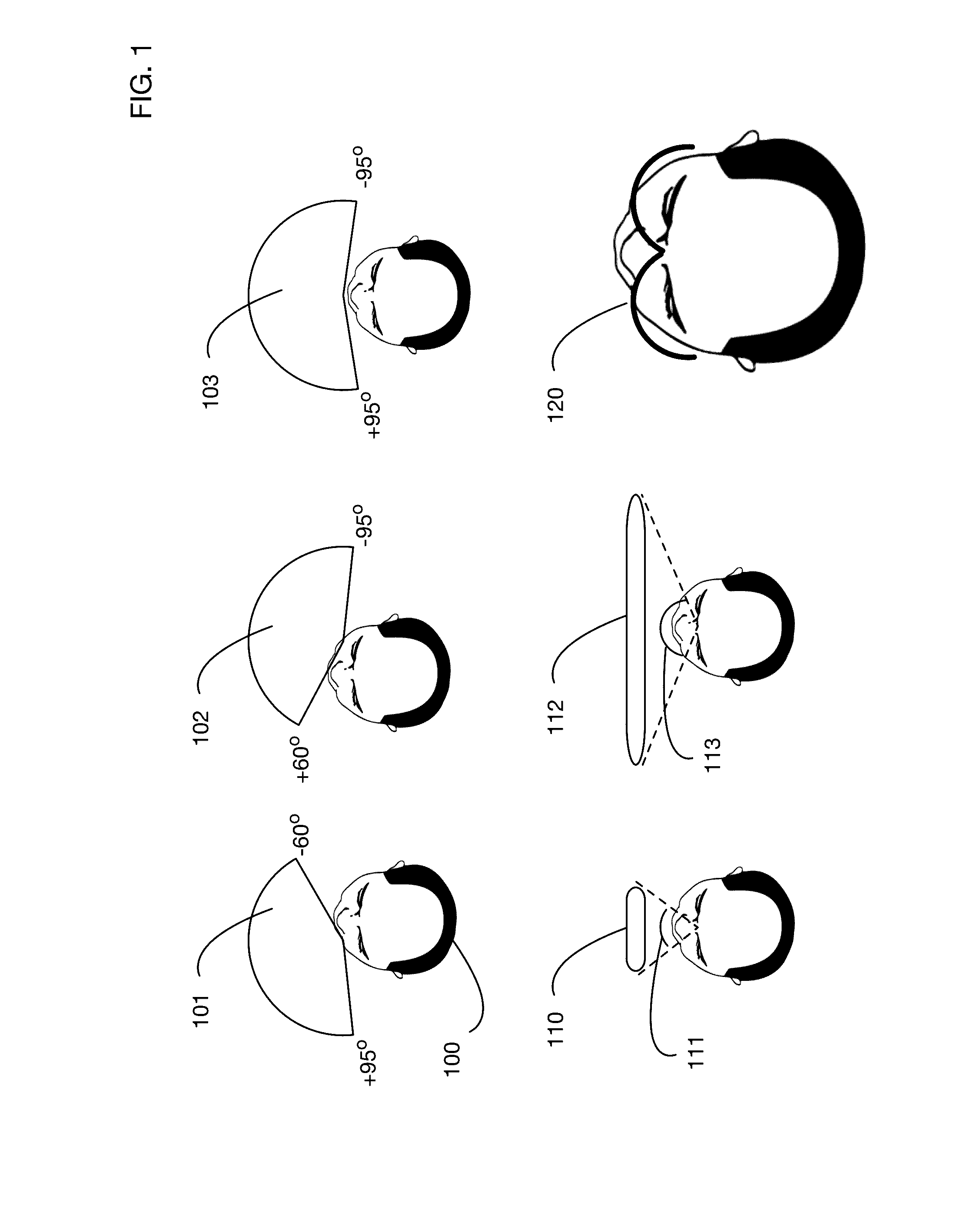
[0046]FIG. 1 illustrates the challenge of providing a wide field-of-view display for a head mounted device. A typical user has a horizontal field of view 101 for the left eye an...


PUM


Abstract

A display system for a head mounted device that illuminates the peripheral regions of the user's field of view to enhance an immersive experience. The system may use peripheral light emitters to the left and right of one or more central displays. Peripheral light emitters may provide lower resolution images, or only with vertical resolution, corresponding to the user's lower resolution vision in these peripheral regions. Reflective surfaces and lenses may be used to direct peripheral light into desired shapes and patterns. Rendering of peripheral light colors and intensities at each peripheral pixel may use approximations for improved performance since users may not be sensitive to precise color values in the peripheral regions.

Description

[0001]This application is a continuation in part of U.S. Utility patent application Ser. No. 14 / 820,774, filed Aug. 7, 2015, the specification of which is hereby incorporated herein by reference.BACKGROUND OF THE INVENTION[0002]Field of the Invention[0003]One or more embodiments of the invention are related to the field of virtual reality systems. More particularly, but not by way of limitation, one or more embodiments of the invention enable a head mounted display system that uses a peripheral field-of-view illumination system to create an immersive image covering a significant portion of a user's natural field of view.[0004]Description of the Related Art[0005]Virtual reality systems are known in the art. Such systems generate a virtual world for a user that responds to the user's movements. Examples include various types of virtual reality headsets and goggles worn by a user, as well as specialized rooms with multiple displays. Virtual reality systems typically include sensors tha...

Claims


Application Information

Patent Timeline
Patent Type & Authority Applications(United States)
IPC IPC(8): G02B27/01F21V21/084F21V5/00G06T19/00G06T15/50G06T17/20G06T15/04F21V7/00F21V5/04
CPCG02B27/0172F21V7/0075F21V21/084F21V5/006F21V5/045G02B2027/0174G06T17/20G06T15/04G06T19/006G02B2027/0123G02B2027/0134G06T15/506G02B2027/0147H04N13/324H04N13/344G06T3/40G06T15/50
Inventor PASSMORE, CHARLES GREGORYLI, ADAM
Owner KAYA DYNAMICS LLC
Why Eureka
Try Eureka