Feedback control device

a control device and feedback technology, applied in the direction of electrical controllers, program control, separation processes, etc., can solve the problems of control becoming unstable, digital schemes may not satisfy the responsivity depending on the controlled object, etc., to achieve high stability of feedback control, high processing speed, and easy implementation of complex processing

Active Publication Date: 2017-02-16
SHIMADZU CORP
View PDF29 Cites 1 Cited by
  • Summary
  • Abstract
  • Description
  • Claims
  • Application Information

AI Technical Summary

Benefits of technology

[0013]Stability of feedback control is high because P control can be performed by using an electric circuit independent of I control. Also, complicated processing can be implemented easily because I control is performed by digital processing.
[0014]In contrast, the scheme of Patent Document 3 or 4, which performs all PI control by digital processing, has a problem in responsivity depending on the controlled object. For example, for pressure control, the P control requires about 1-millisecond responsivity, and such high-speed processing is difficult from a viewpoi...

Problems solved by technology

Among these schemes, the analog scheme may need a complicated, large-scale control circuit depending on the controlled object as will be described later, and control may become ...

Method used


Image

  • Feedback control device
  • Feedback control device
  • Feedback control device

Examples


Embodiment Construction

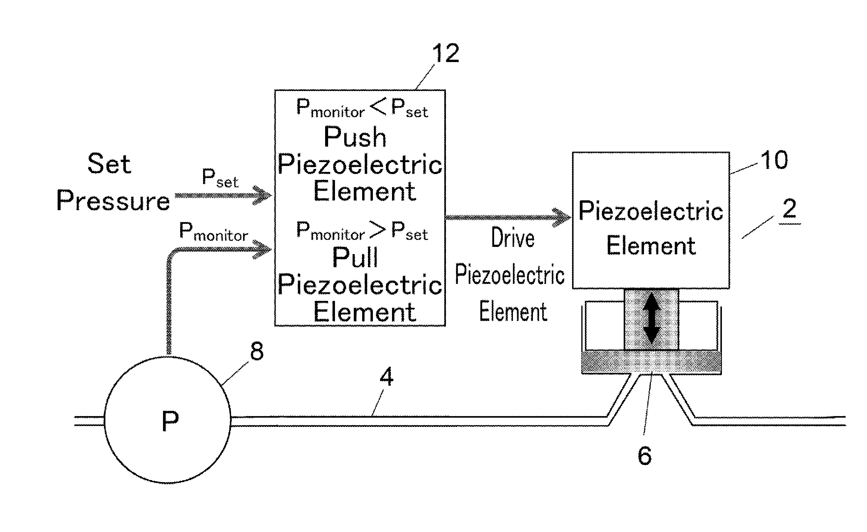
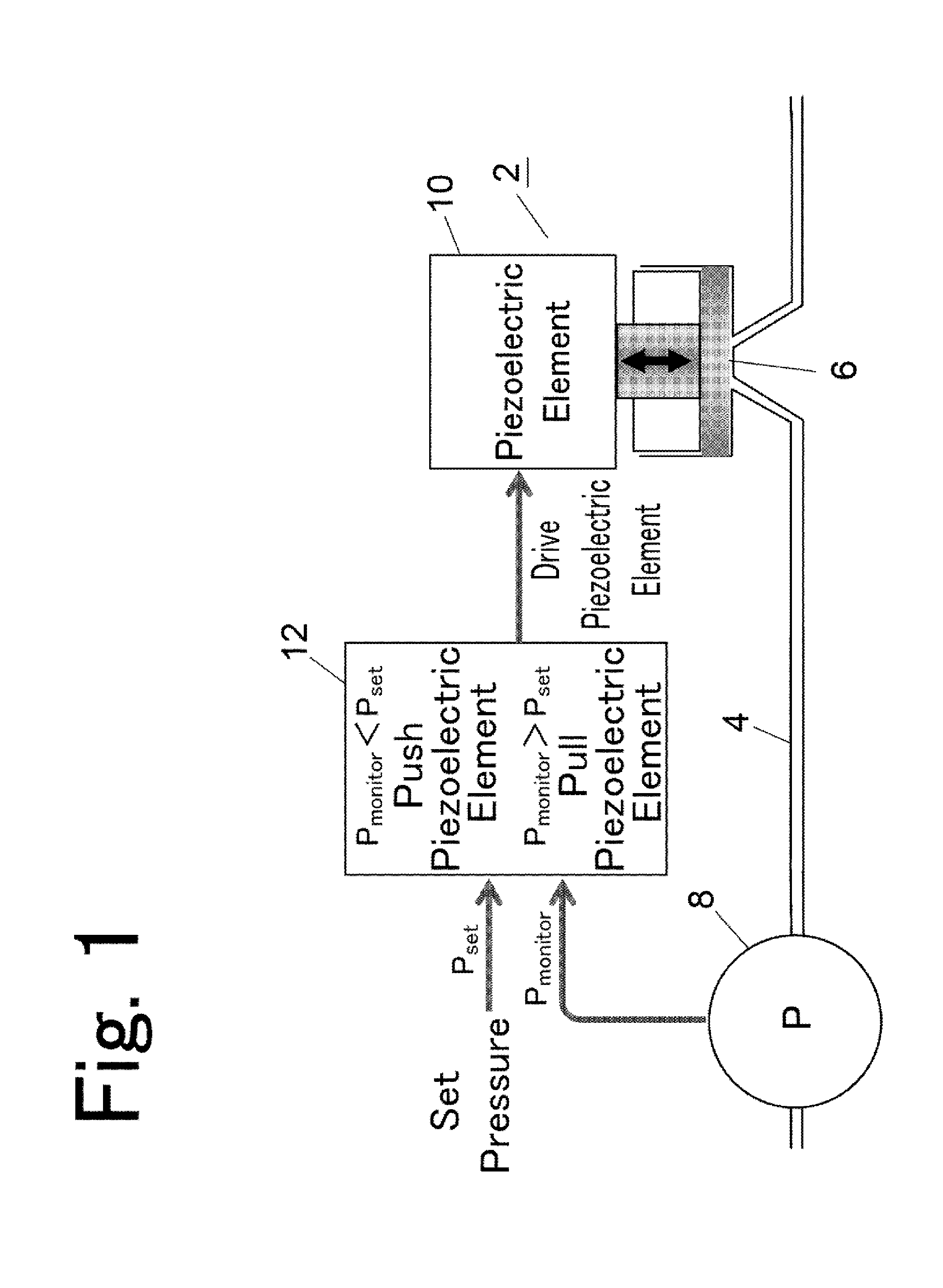
[0031]In the present invention, a preferred form for further simplifying a circuit configuration is a configuration in which an I control unit is connected to a P control circuit so that an I control component VI is input into one input terminal of the differential amplifier circuit together with a detection value of the detector, and an output terminal of the differential amplifier circuit is connected to the driver element.

[0032]In one preferred exemplary embodiment, the I control unit further includes a threshold holding unit that holds a threshold VP_upper with respect to a deviation of the detection value from a target value, and a first comparison unit that resets the I control component VI of output to zero when the deviation exceeds the threshold VP_upper held in the threshold holding unit, and continues integration of the deviation when the deviation is equal to or less than the threshold VP_upper held in the threshold holding unit.

[0033]In another preferred exemplary embod...


PUM


Abstract

A feedback control apparatus includes: a detector configured to detect an output value based on a controlled object; a P control circuit including a differential amplifier circuit and an analog circuit, the differential amplifier circuit being configured to receive a detection value of the detector and a target value, the analog circuit being configured to output a P control component VP to an output of the differential amplifier circuit; an I control unit configured to output an I control component VI by integrating a deviation of the detection value from the target value by digital processing; and a driver element configured to be driven based on the P control component VP from the P control circuit and the I control component VI from the I control unit to control the controlled object.

Description

TECHNICAL FIELD[0001]The present invention relates to an apparatus that performs feedback control on a controlled object by a PI control scheme. Such a controlled object is widespread. Examples in an analyzer field include an apparatus that adjusts pressure and a flow rate in a flow channel such as a pressure-regulating valve, a pressure regulator, a back pressure regulator, a back pressure-regulating valve, and a flow controller. Examples in a field of manufacturing apparatus field include a semiconductor manufacturing apparatus and a positioning apparatus of a movable body in an industrial robot or NC machine. However, the controlled object to which the present invention is applied is not limited to these examples.BACKGROUND ART[0002]When a pressure control apparatus used in a super-critical fluid chromatograph (SFC) or super-critical fluid extractor (SFE) is cited as an example of controlled object, this apparatus performs feedback control on a degree of opening of the back press...

Claims


Application Information

Patent Timeline
IPC IPC(8): G01N30/32G05D16/20G05B11/42
CPCG01N30/32G05B11/42G01N2030/328G05B2219/41316G05D16/2013B01D15/40G05B19/46G05B2219/42034G05D16/024
Inventor GOTO, HIROOMIINOUE, TSUNEHIROMORI, TAKAHIRO
Owner SHIMADZU CORP
Why Eureka
Try Eureka