
Fuse-enabled secure BIOS mechanism with override feature

Active Publication Date: 2017-02-16
VIA TECH INC
View PDF19 Cites 17 Cited by
  • Summary
  • Abstract
  • Description
  • Claims
  • Application Information

AI Technical Summary

Benefits of technology

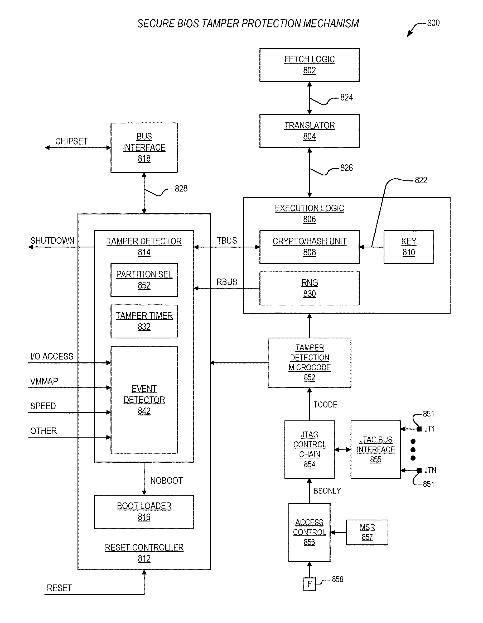
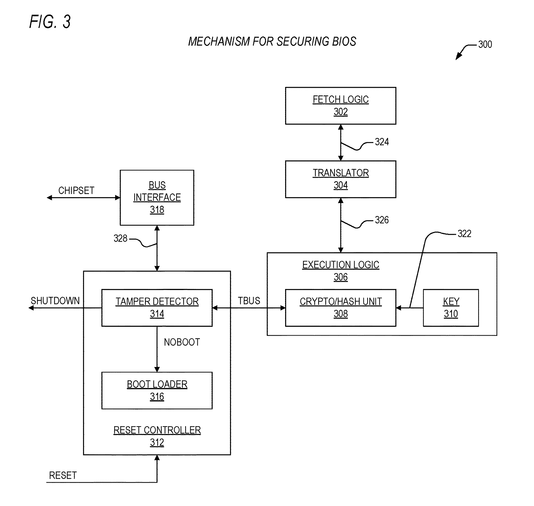
The present invention provides a superior technique for protecting a computing system's basic input / output system (BIOS) from attacks. It includes an apparatus and method for storing BIOS contents as plaintext in a BIOS ROM along with an encrypted message digest that corresponds to the BIOS contents. The apparatus includes a tamper detector, a random number generator, a JTAG control chain, a fuse, a machine specific register, and an access control element. The method involves storing the BIOS contents as plaintext in the BIOS ROM, indicating whether programming of a combination of prescribed intervals and event occurrences is to be disabled, storing a value in a machine specific register, determining that the fuse is blown, directing the JTAG control chain to enable programming of the combination of prescribed intervals and event occurrences if the value matches an override value within the access control element, generating a random number at completion of a current BIOS check, and precluding operation of the microprocessor if the second message digest and decrypted message digest are not equal. The technical effects of the invention include improved protection against attacks on the BIOS, increased efficiency in programming, and improved reliability and security of the computing system.

Problems solved by technology

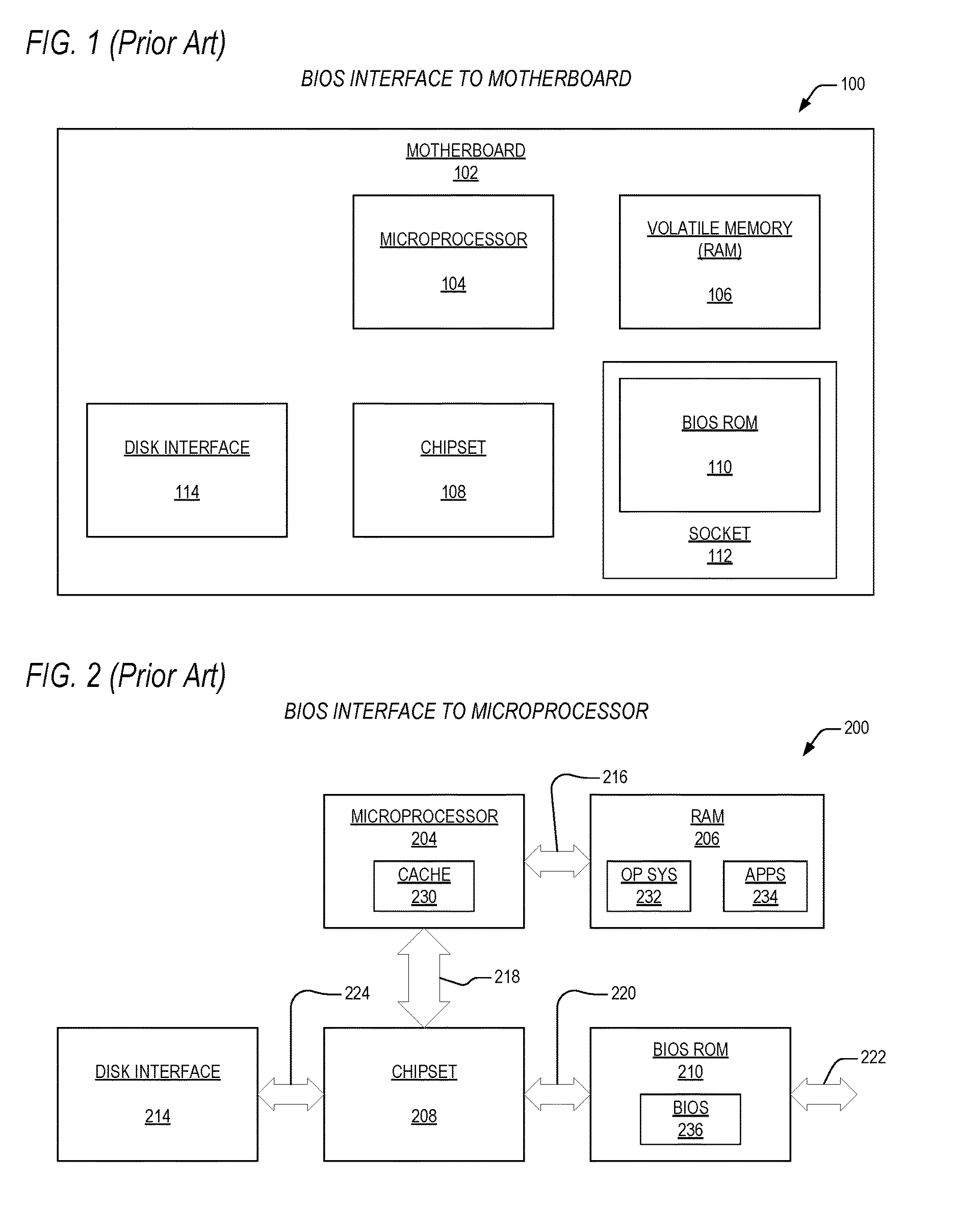
Because BIOS contains security data, it is typically a target for hackers and the like.
By modifying a system's BIOS, for example, an unauthorized user may be able to execute programs without a license.
Some attempts at achieving one or both of the above objectives have resulted in mechanisms that are limiting.
For example, moving BIOS storage onto the same die as the system's microprocessor protects it from tampering, yet totally defeats the ease of upgrade objective because the BIOS no longer is physically accessible.
Other techniques resort to encryption of BIOS contents, which is advantageous from a protection perspective, but which cripple the performance of a system because of the unacceptable number of operations that are required to decrypt BIOS contents each time it is used.

Method used


Image

  • Fuse-enabled secure BIOS mechanism with override feature
  • Fuse-enabled secure BIOS mechanism with override feature
  • Fuse-enabled secure BIOS mechanism with override feature

Examples


Embodiment Construction

[0027]Exemplary and illustrative embodiments of the invention are described below. In the interest of clarity, not all features of an actual implementation are described in this specification, for those skilled in the art will appreciate that in the development of any such actual embodiment, numerous implementation-specific decisions are made to achieve specific goals, such as compliance with system-related and business related constraints, which vary from one implementation to another. Furthermore, it will be appreciated that such a development effort might be complex and time-consuming, but would nevertheless be a routine undertaking for those of ordinary skill in the art having the benefit of this disclosure. Various modifications to the preferred embodiment will be apparent to those skilled in the art, and the general principles defined herein may be applied to other embodiments. Therefore, the present invention is not intended to be limited to the particular embodiments shown a...


PUM


Abstract

An apparatus is provided for protecting a basic input / output system (BIOS) in a computing system. The apparatus includes a BIOS read only memory (ROM), a tamper detector, a random number generator, a JTAG control chain, a fuse, a machine specific register, and an access controller. The BIOS ROM includes BIOS contents stored as plaintext, and an encrypted message digest, where the encrypted message digest has an encrypted version of a first message digest that corresponds to the BIOS contents. The tamper detector is operatively coupled to the BIOS ROM, and is configured to generate a BIOS check interrupt at a combination of prescribed intervals and event occurrences, and is configured to access the BIOS contents and the encrypted message digest upon assertion of the BIOS check interrupt, and is configured to direct a microprocessor to generate a second message digest corresponding to the BIOS contents and a decrypted message digest corresponding to the encrypted message digest, and is configured to compare the second message digest with the decrypted message digest, and is configured to preclude the operation of the microprocessor if the second message digest and the decrypted message digest are not equal. The random number generator disposed within the microprocessor, and generates a random number at completion of a current BIOS check, which is employed to set a following prescribed interval, whereby the prescribed intervals are randomly varied. The JTAG control chain is configured to program the combination of prescribed intervals and event occurrences within tamper detection microcode storage. The fuse is configured to indicate whether programming of the combination of prescribed intervals and event occurrences is to be disabled. The machine specific register is configured to store a value therein. The access control element is coupled to the fuse, the machine specific register, and the JTAG control chain, and is configured to determine that the fuse is blown, and configured to direct the JTAG control chain to enable programming of the combination of prescribed intervals and event occurrences if the value matches an override value within the access control element during a period that the value is stored within the machine specific register.

Description

CROSS-REFERENCE TO RELATED APPLICATIONS[0001]This application is a continuation-in-part of the following U.S. Patent Application:SERIAL FILINGNUMBERDATETITLE14079087Nov. 13, 2013SECURE BIOS MECHANISM IN A (CNTR.2630)TRUSTED COMPUTING SYSTEM[0002]This application is related to the following co-pending U.S. Patent Applications, each of which has a common assignee and common inventors.SERIAL FILINGNUMBERDATETITLE14079021Nov. 13, 2013APPARATUS AND METHOD FOR SECURING BIOS IN(CNTR.2629)A TRUSTED COMPUTING SYSTEM——PROGRAMMABLE SECURE BIOS MECHANISM IN A(CNTR.2630-CP1)TRUSTED COMPUTING SYSTEM——JTAG-BASED SECURE BIOS MECHANISM IN A(CNTR.2630-CP2)TRUSTED COMPUTING SYSTEM——FUSE-ENABLED SECURE BIOS MECHANISM IN A(CNTR.2630-CP3)TRUSTED COMPUTING SYSTEM14079145Nov. 13, 2013EVENT-BASED APPARATUS AND METHOD FOR(CNTR.2634)SECURING BIOS IN A TRUSTED COMPUTINGSYSTEM DURING EXECUTION14079226Nov. 13, 2013PARTITION-BASED APPARATUS AND METHOD FOR(CNTR.2635)SECURING BIOS IN A TRUSTED COMPUTINGSYSTEM DURIN...

Claims


Application Information

Patent Timeline
IPC IPC(8): G06F21/57G06F21/78H04L9/06
CPCG06F21/572G06F21/78H04L9/0643H04L9/0631G06F2221/2139
Inventor HENRY, G. GLENN
Owner VIA TECH INC
Learn More