Ultrasonic image diagnostic device, ultrasonic image processing method, and ultrasonic image processing program

Active Publication Date: 2017-02-23
KONICA MINOLTA INC
View PDF13 Cites 8 Cited by
  • Summary
  • Abstract
  • Description
  • Claims
  • Application Information

AI Technical Summary

Benefits of technology

The present invention aims to improve the reliability of evaluating the motion of a moving body in an ultrasonic image. This is achieved through an ultrasonic image diagnostic device, an ultrasonic image processing method, and an ultrasonic image processing program.

Problems solved by technology

Therefore, there is certain limitation in improvement of reliability of motion evaluation of the moving body in the ultrasonic image.

Method used


Image

  • Ultrasonic image diagnostic device, ultrasonic image processing method, and ultrasonic image processing program
  • Ultrasonic image diagnostic device, ultrasonic image processing method, and ultrasonic image processing program
  • Ultrasonic image diagnostic device, ultrasonic image processing method, and ultrasonic image processing program

Examples


Embodiment Construction

[0025]Hereinafter, an embodiment of the present invention will be described in detail with reference to the drawings. However, the scope of the invention is not limited to the illustrated examples.

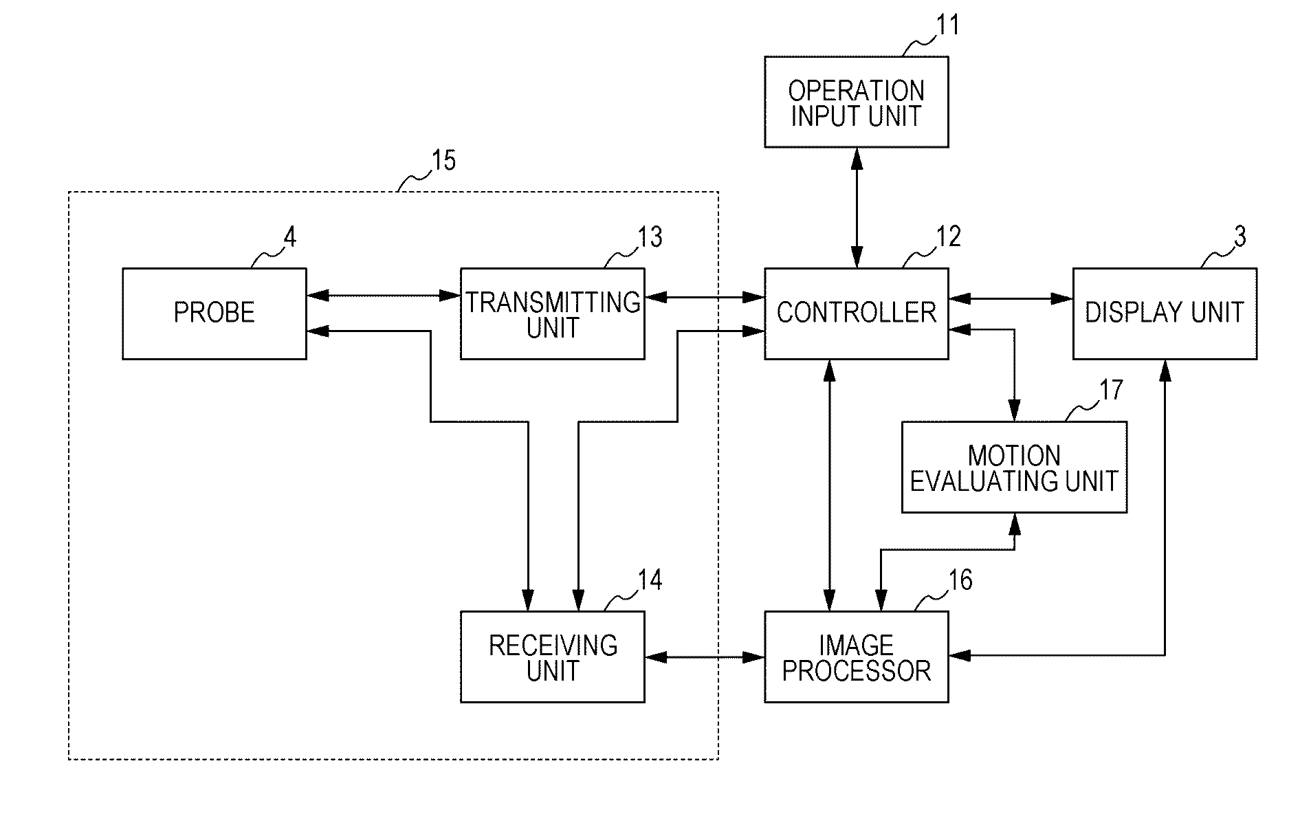
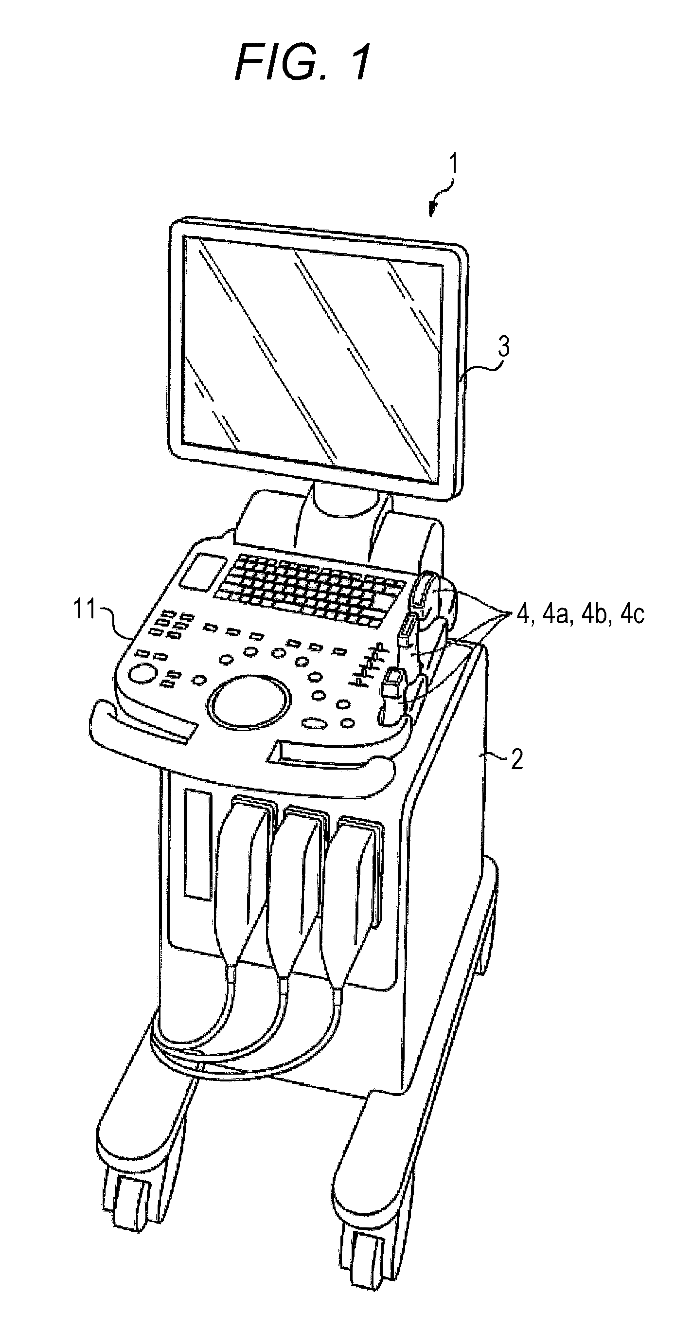
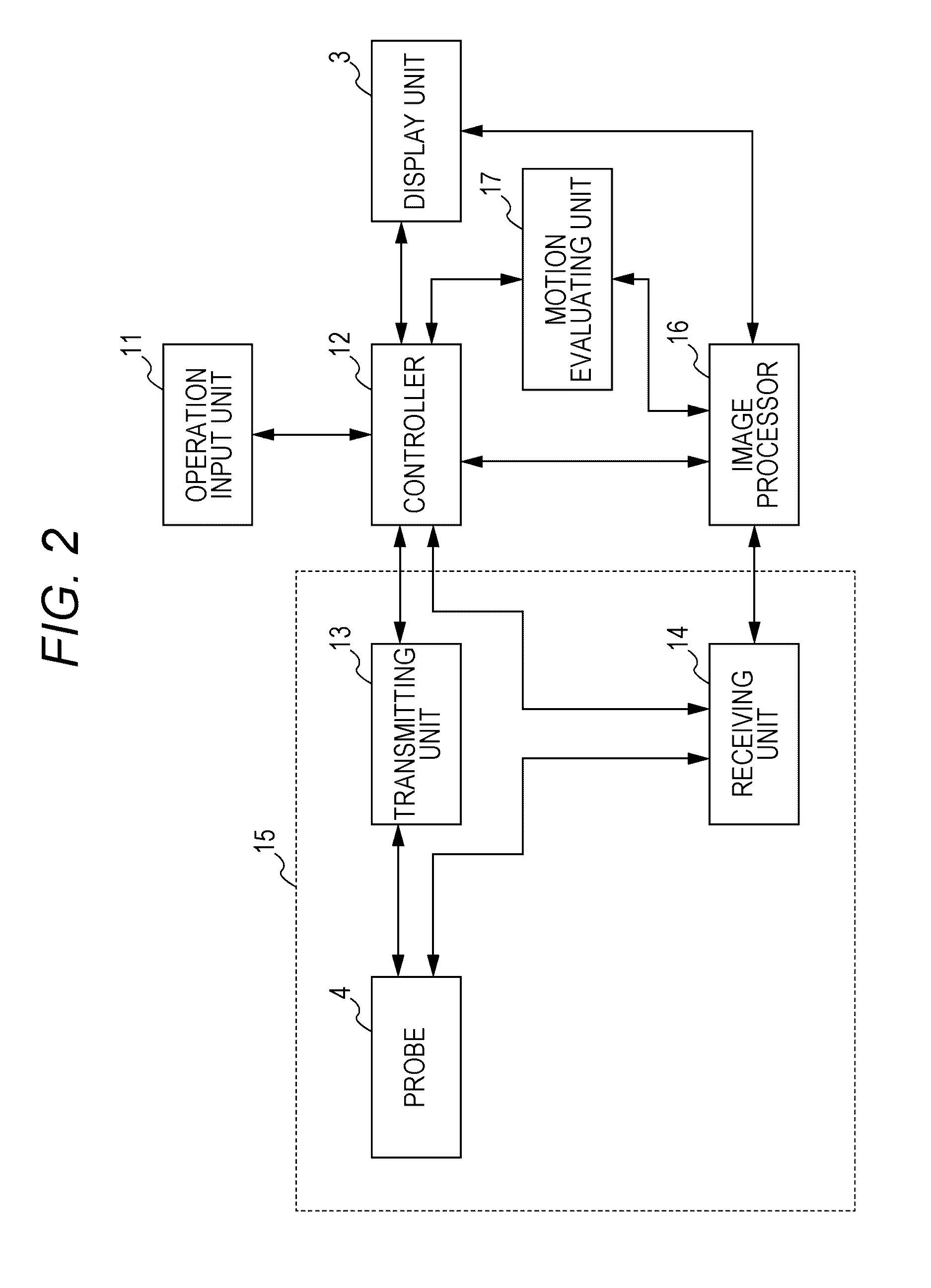
[0026]FIG. 1 is a perspective view illustrating an appearance of an ultrasonic image diagnostic device 1 according to one embodiment of the present invention. FIG. 2 is a block diagram illustrating a schematic configuration of the ultrasonic image diagnostic device 1 according to this embodiment. As illustrated in FIG. 1, the ultrasonic image diagnostic device 1 according to this embodiment is provided with a device main body 2, a display unit 3, three types of probes 4a, 4b, and 4c (hereinafter, collectively represented by “4”), and an operation input unit 11. The display unit 3 being a display in which a liquid crystal panel is used, for example, is mainly used for displaying an ultrasonic image. The probe 4 is combination of the three types of probes: an electronic linear probe which em...


PUM


Abstract

An ultrasonic image diagnostic device includes: an ultrasonic transmitting / receiving unit which repeatedly transmits an ultrasonic wave to a subject and receives an ultrasonic echo from the subject; an image processor which generates a plurality of ultrasonic images illustrating an in-vivo state of the subject based on ultrasonic echoes sequentially received from the subject; and a motion evaluating unit which performs motion evaluation of a moving body in the plurality of generated ultrasonic images, wherein the motion evaluating unit includes an interval setting unit which sets an interval between the ultrasonic images which should be compared with each other for the motion evaluation so as to be variable in increments of the number of frames based on a frame rate of the plurality of generated ultrasonic images.

Description

[0001]The entire disclosure of Japanese Patent Application No. 2015-163479 filed on Aug. 21, 2015 including description, claims, drawings, and abstract are incorporated herein by reference in its entirety.BACKGROUND OF THE INVENTION[0002]Field of the Invention[0003]The present invention relates to an ultrasonic image diagnostic device, an ultrasonic image processing method, and an ultrasonic image processing program.[0004]Description of the Related Art[0005]In ultrasonic diagnosis, when applying an ultrasonic probe on a body surface of a subject to capture an in-vivo ultrasonic image, there is a case of making a puncture for removing body fluid accumulated in an in-vivo imaging area or injecting medical solution to the area. At that time, positional relationship between a puncture needle and an organ in the body is confirmed by using the ultrasonic image displayed on a screen.[0006]Conventionally, it is suggested to process the ultrasonic image such that the puncture needle in the d...

Claims


Application Information

Patent Timeline
IPC IPC(8): A61B8/08A61B8/00A61B8/14
CPCA61B8/5276A61B8/5207A61B8/461A61B8/14A61B8/54
Inventor SHIKAMA, JOTAKAGI, KAZUYATAKEDA, YOSHIHIRO
Owner KONICA MINOLTA INC
Why Eureka
Try Eureka