Electron beam melting and cutting composite 3D printing apparatus

a 3d printing and composite technology, applied in the field of 3d (three-dimensional) printing apparatuses, can solve the problems of large shape error of forming components, poor surface finish, and large so as to reduce the stress deformation of structural components caused by temperature variation during the forming process, and reduce the heat effect of other elements

Active Publication Date: 2017-02-23
YUANMENG PRECISION TECH SHENZHEN INST
View PDF9 Cites 10 Cited by
  • Summary
  • Abstract
  • Description
  • Claims
  • Application Information

AI Technical Summary

Benefits of technology

[0017]Compared with the prior art, the electron beam melting and cutting composite 3D printing apparatus provided by the present application uses the powder spreading structure to spread metal powder onto the Z-direction movable platform to form a metal powder layer, and uses the emitting head of the electron beam gun to emit an electron beam to melt the metal powder layer on the Z-direction movable platform, thereby forming a structural component. Besides, along with the movement of the Y-direction movable platform, the Z-direction movable platform is moved to a position below the cutting structure; by the movement of the cutting heading of the cutting structure in space, the structural component on the Z-direction movable platform is cut, such that properties, such as surface accuracy, of the machined structural component meet the usage requirements. Besides, since shielding is formed between the emitting head of the electron beam gun and the Z-direction movable platform, when the electron beam gun emits an electron beam to perform melting machining, the generated heat of the high temperature is confined in the shielding case, which reduces the heat effect on other elements inside the cavity. Moreover, when using the cutting head to perform cutting machining, it can ensure that the temperature in the cutting area is constant, and thus the stress deformation of the structural component caused by a temperature variation during the forming process is reduced.

Problems solved by technology

However, the formed component has a large shape error and a poor surface finish; therefore, the formed component needs to be machined secondarily using a traditional machining method, only by this can the component obtain a shape and a surface accuracy meeting the requirements of aviation manufacturing industry.
However, the electron beam gun has to be used in a vacuum environment and a high temperature is generated during the forming process; therefore, the cutting manners in the vacuum environment may be greatly restricted; firstly, the high temperature generated when the electron beam gun melts the metal powder has a heat effect on other elements inside the vacuum chamber; secondarily, due to the temperature variation in the vacuum chamber the structural component will undergo stress deformation during the cutting process.

Method used


Image

  • Electron beam melting and cutting composite 3D printing apparatus
  • Electron beam melting and cutting composite 3D printing apparatus
  • Electron beam melting and cutting composite 3D printing apparatus

Examples


Embodiment Construction

[0022]In order to make the objective, the technical solution and the advantages of the present application more clear, the present application is further explained in detail with reference to the accompanying drawings and embodiments. It should be understood that, the specific embodiments described herein are only used for explaining the present application, and are not a limitation to the present application.

[0023]The implementation of the present application is described in detail with reference to the specific embodiments in the following.

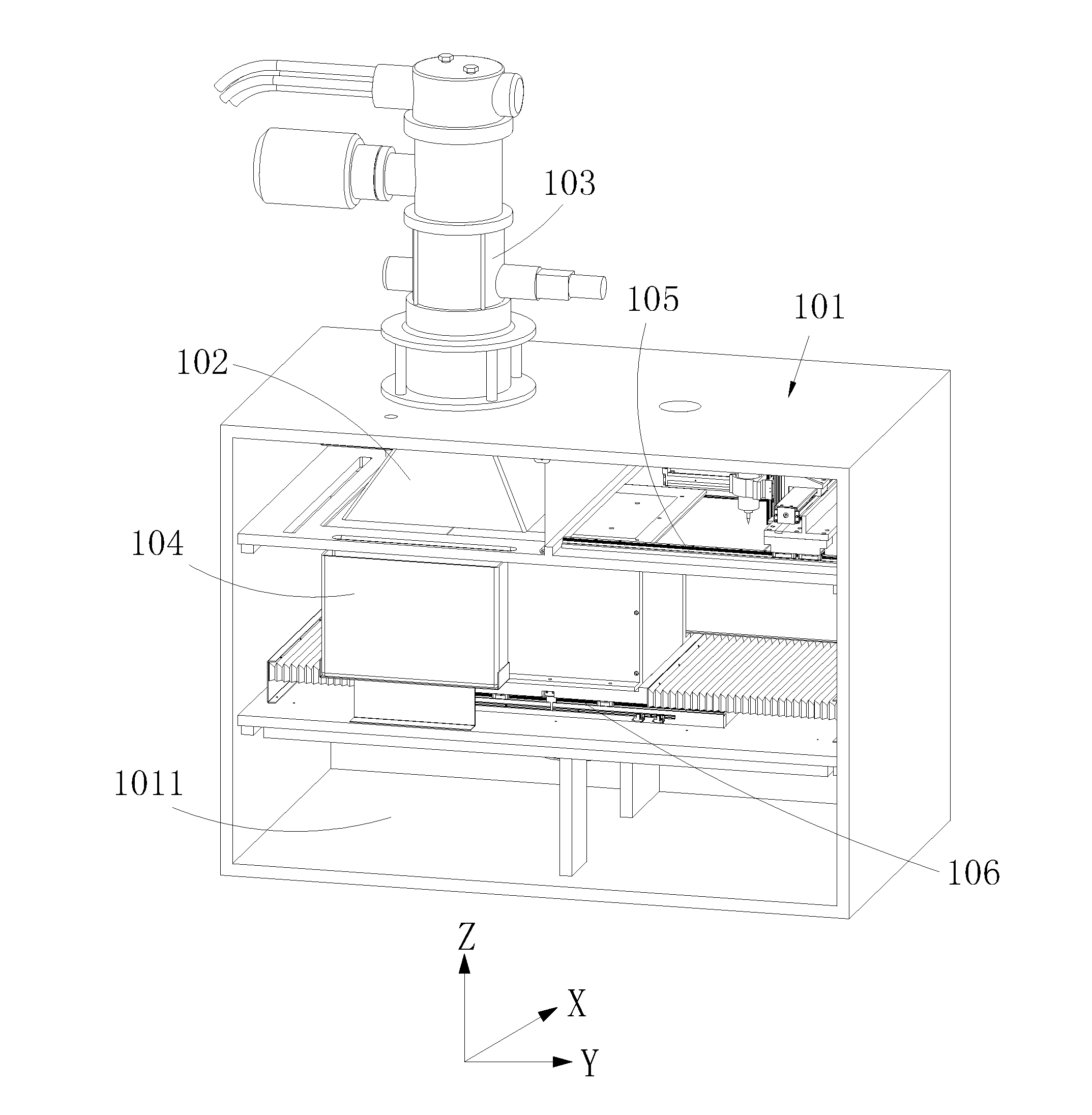
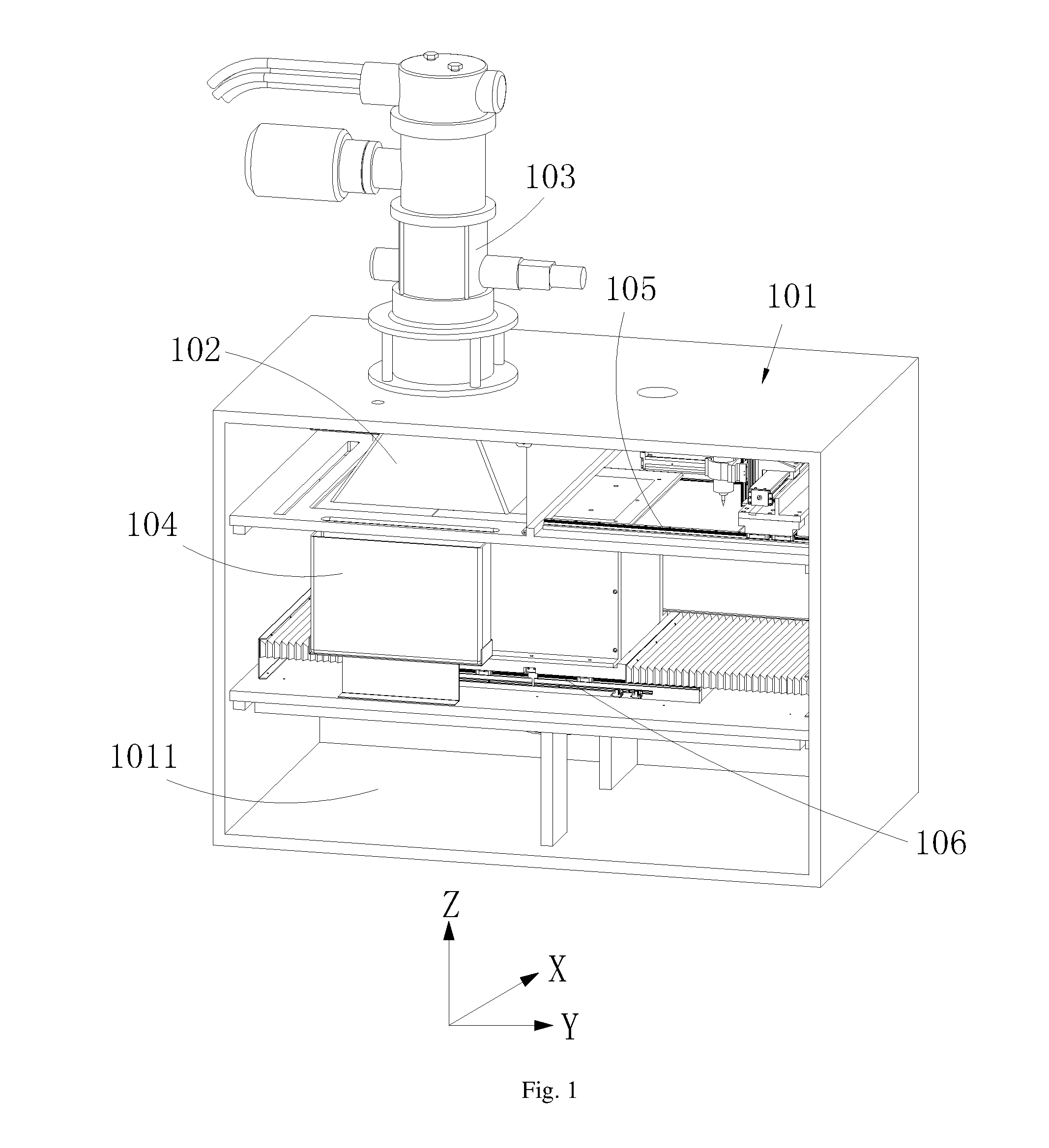
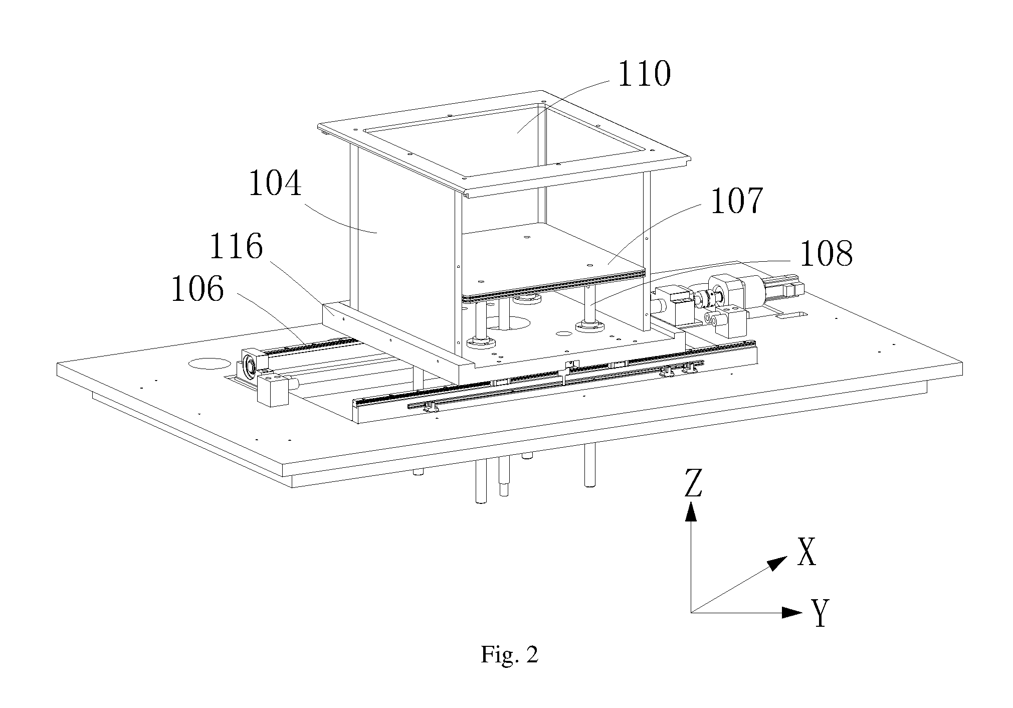
[0024]FIGS. 1-4 show a preferred embodiment provided by the present application.

[0025]An electron beam melting and cutting composite 3D printing apparatus provided by the present embodiment comprises a box 101, an electron beam gun 103, a cutting structure, a first Y-direction guide rail 106 and a Y-direction movable platform 116. The box 101 has a cavity in a vacuum state formed therein. In this case, the vacuum state means that the environment...


PUM

PropertyMeasurementUnit
vacuum stateaaaaaaaaaa
areaaaaaaaaaaa
strengthaaaaaaaaaa

Abstract

The present application relates to the technical field of 3D printing apparatus, and discloses an electron beam melting and cutting composite 3D printing apparatus which comprises a box and an electron beam gun, in which the box has a cavity formed therein, the cavity is provided therein with a cutting structure, a first Y-direction guide rail and a Y-direction movable platform, the electron beam gun has an emitting head formed in the cavity, the Y-direction movable platform is provided thereon with a Z-direction movable platform, the Z-direction movable platform is provided thereon with a powder spreading structure, the cutting structure has a cutting head, a shielding case is arranged between the emitting head and the Z-direction movable platform, the emitting head of the electron beam gun is inserted in an upper opening of the shielding case, and a lower opening of the shielding case is aligned with the Z-direction movable platform.

Description

TECHNICAL FIELD[0001]The present application relates to the technical field of 3D (three-dimensional) printing apparatuses, and more particularly, relates to an electron beam melting and cutting composite 3D printing apparatus.BACKGROUND[0002]Metal melting 3D printing technology (Selective Laser Melting, SLM) is a kind of technology using high-brightness laser to directly melt metal power materials, and directly forming a component with any complicated structure, which has properties similar to a casting, via a 3D model, without adhesives.[0003]By means of the metal melting 3D printing technology, a component having a strength level reaching that of a casting can be formed. However, the formed component has a large shape error and a poor surface finish; therefore, the formed component needs to be machined secondarily using a traditional machining method, only by this can the component obtain a shape and a surface accuracy meeting the requirements of aviation manufacturing industry.[...

Claims


Application Information

Patent Timeline
Patent Type & Authority Applications(United States)
IPC IPC(8): B23K15/00B33Y30/00B33Y40/00B23K15/08
CPCB23K15/0086B23K15/08B33Y40/00B33Y30/00B23K15/002B22F2003/247B22F2201/20Y02P10/25B22F12/38B22F12/33B22F12/222B22F10/28B22F12/224B22F10/66B22F10/32B22F12/30
Inventor LI, JUNQILIU, QINGXU, YIOUYANG, MIAOANNIE, YANYANG, HU
Owner YUANMENG PRECISION TECH SHENZHEN INST
Why Eureka
Try Eureka