
Surface or Submersible Sluiceable Filtration System for Hazardous or Radioactive Waste Water

a filtration system and radioactive waste water technology, applied in water treatment multi-stage treatment, water treatment from quaries, water treatment water nature, etc., can solve the problems of unfavorable environmental protection, unfavorable environmental protection, and inability to backwash, etc., to achieve the effect of high remaining dos

Active Publication Date: 2017-02-23
MTN GRP LLC
View PDF0 Cites 8 Cited by
  • Summary
  • Abstract
  • Description
  • Claims
  • Application Information

AI Technical Summary

Benefits of technology

The patent is about a system that can be used to treat water with hazardous or radioactive materials. The system can be placed either on the surface or under water and can handle a variety of treatment methods. One challenge is the sluicing of granular materials, which the system solves by using an eductor system that allows the media to be fully utilized and the vessel to be cleaned after each processing cycle. The system also includes a motive force eductor to keep the media fluidized and moving, preventing clogging of lines. Overall, the system provides a safe and efficient way to treat water with hazardous materials.

Problems solved by technology

Most systems in the past attempting such evacuation have a dead space of media remaining in the bottom of the vessel below the internal laterals that is not possible to either back wash (float) or evacuate (sluice) at the end of a processing cycle.
It also replaces the standard sluice tube extending from top to bottom which only has a suction mode from above the system making them an inefficient method of sluicing out difficult to mobilize media.
Grinder pumps, or any impeller type pump, can be very efficient in moving solids; but, of course, this causes fracturing of the media and undesired fines introduction into the system.
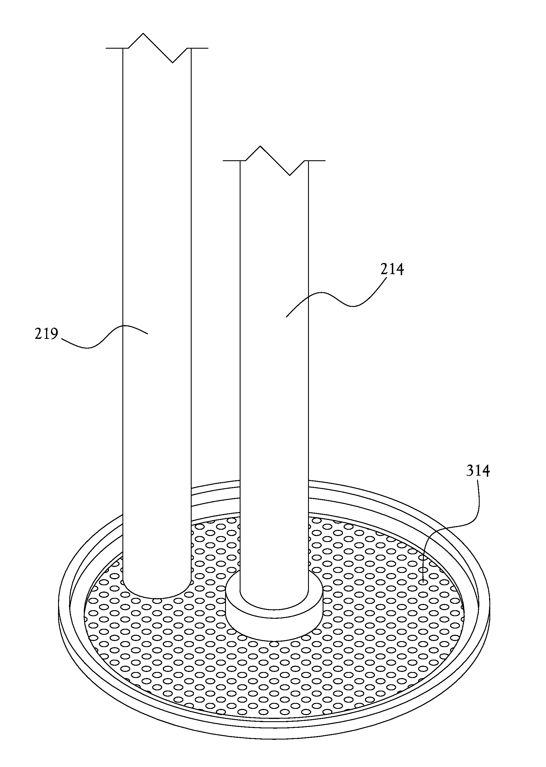
This top screen has three very close tolerance openings though it allowing these three tubes to penetrate but not allowing media above that portion of the vessel.

Method used


Image

  • Surface or Submersible Sluiceable Filtration System for Hazardous or Radioactive Waste Water
  • Surface or Submersible Sluiceable Filtration System for Hazardous or Radioactive Waste Water
  • Surface or Submersible Sluiceable Filtration System for Hazardous or Radioactive Waste Water

Examples


Embodiment Construction

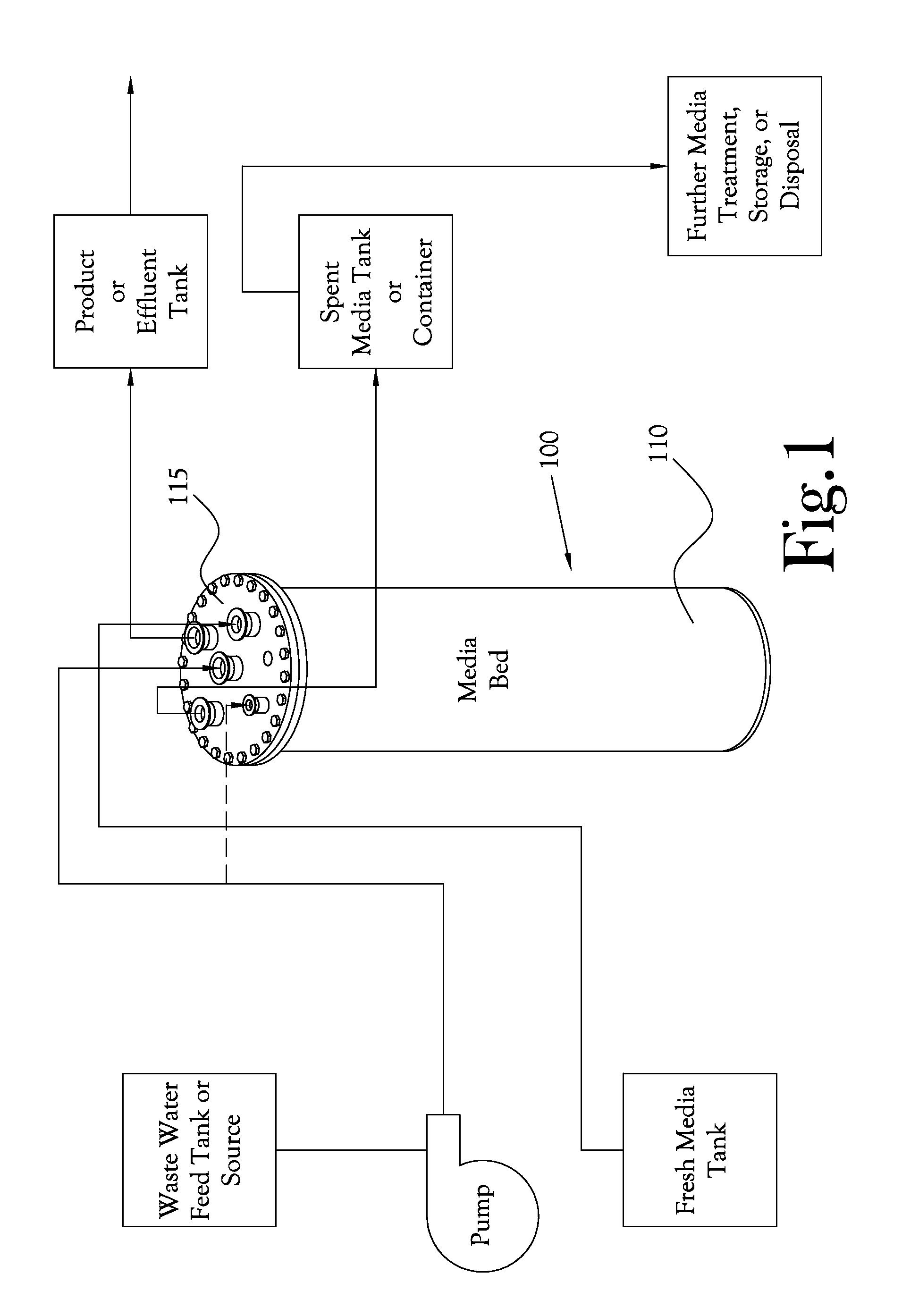
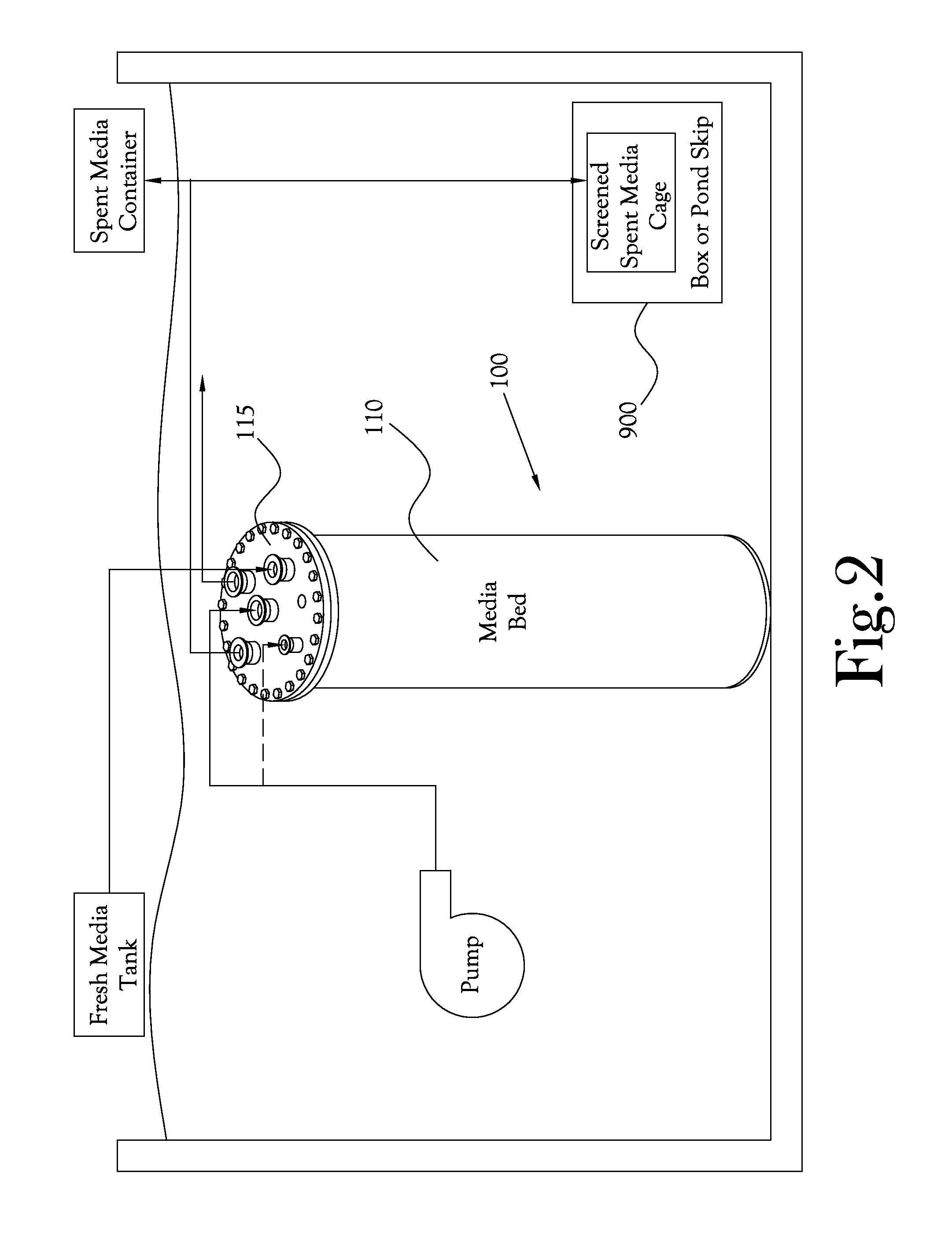
[0064]Disclosed herein is a surface or submersible sluiceable system for use in removing hazardous ions (hereinafter “contaminants”) and radioactive isotopes (hereinafter “target isotopes”) from a fluid stream, such as a fluid stream from the primary coolant or secondary waste stream loop of a nuclear reactor system or a fluid stream from a spent-fuel pool, pond or vault. Generally, these systems are adapted to be surface skid-mounted systems or submersed in the fluid stream, and additionally in many embodiments the sluiceable systems are adapted to be reused with only the sluiced media being stored (above ground or under water), allowing for further treatment or for final disposal. Further treatment results in a stabilized, non-leaching final waste product with a substantially reduced volume compared to the original waste stream. Only the least expensive component, the media, is disposed of greatly saving on decontamination, storage space and extremely expensive and limited disposa...


PUM


Abstract

Surface or submersible sluiceable system for use in removing hazardous contaminants or radioactive isotopes from a fluid stream, such as a fluid stream from the primary coolant loop or secondary loop of a nuclear reactor system, a fluid stream from a spent-fuel pool or pond or hazardous or radioactive contaminants in ground water. Generally, this surface or submersible sluiceable system is adapted to be utilized in a surface skid or submersed in the fluid stream, and additionally the vessels are adapted to be sluiced and reused after use, resulting in a potentially stabilized, non-leaching final waste product with a substantially reduced volume for storage or disposal. The system can be utilized with any type of media, whether standard ion exchange beads or inorganic granular media.

Description

CROSS-REFERENCE TO RELATED APPLICATIONS[0001]This Application claims the benefit of U.S. Provisional Patent Application No. 62 / 208,274, filed Aug. 21, 2015, the entire content of which is incorporated herein by reference.STATEMENT REGARDING FEDERALLY-SPONSORED RESEARCH OR DEVELOPMENT[0002]Not ApplicableBACKGROUND OF THE INVENTION[0003]1. Field of Invention[0004]The present invention relates generally to the treatment of hazardous and radioactive waste and in particular to processing waste water from nuclear power reactors and other sources of radioactive waste materials as well as mining waste water and groundwater.[0005]2. Description of the Related Art[0006]It is essential to isolate, contain and stabilize hazardous and radioactive contaminants. The source of these contaminants or isotopes can be normal operation of nuclear power plants in the primary (power generation) or secondary (waste circuit) loops. It can also be from leaks in such systems. Alternatively, hazardous wastes o...

Claims


Application Information

Patent Timeline
IPC IPC(8): C02F1/42B01D15/02
CPCC02F1/42B01D15/02C02F2101/006C02F2301/08C02F2103/10C02F2103/06C02F2103/34
Inventor DENTON, MARKPRINCE, JEFFREY T.
Owner MTN GRP LLC
Learn More