LED light bulb and LED filament thereof

a technology of led filament and led light bulb, which is applied in the field of illumination, can solve the problems of reducing the overall optical efficiency of led lamps, unable to provide illumination with a wide angle range like traditional lamps, and unable to provide illumination with a wide angle range like current led lamps, and achieve the effect of adequate rigidity

Active Publication Date: 2017-02-23
JIAXING SUPER LIGHTING ELECTRIC APPLIANCE
View PDF3 Cites 30 Cited by
  • Summary
  • Abstract
  • Description
  • Claims
  • Application Information

AI Technical Summary

Benefits of technology

[0019]According to some embodiments, each of the surfaces of the LED chips is covered by the light conversion coating. The phosphors of light conversion coating may absorb light out of the surfaces of the LED chips and emit light with longer wavelength. Since the LED chips are surrounded by the light conv

Problems solved by technology

However, due that the luminescence of the LED has directivity, current LED lamps is unable to provide with an illumination with a wide angle range like traditional lamps.
However, the optical components for adjusting the light distribution decrease the overall optical efficiency of LED lamps.
However, the package of LED narrows the illumination angle and decreases optical efficiency.
One of the challenges of LED light bulbs is omnidirectional lighting.
The glass substrate has the advantages of not blocking light emitted from LED chips; however, its disadvanta

Method used


Image

  • LED light bulb and LED filament thereof
  • LED light bulb and LED filament thereof
  • LED light bulb and LED filament thereof

Examples


second embodiment

[0059]Please refer to FIGS. 4 to 5. FIG. 4 illustrates a perspective view of an LED light bulb with partial sectional view according to the LED filament and FIG. 5 illustrates a partial cross-sectional view at section 5-5 of FIG. 4.

[0060]According to the second embodiment of the LED filament 200, the LED filament 200 comprises a plurality of LED chips 202, 204, at least two conductive electrodes 210, 212, and a light conversion coating 220. The conductive electrodes 210, 212 are disposed corresponding to the plurality of LED chips 202, 204. The plurality of LED chips 202, 204 and the conductive electrodes 212, 214 are electrically connected therebetween. The light conversion coating 220 coats on at least two sides of the LED chips 202, 204 and the conductive electrodes 210, 212. The light conversion coating 220 exposes a portion of two of the conductive electrodes 210, 212. The light conversion coating 220 comprises an adhesive 222, a plurality of inorganic oxide nanoparticles 226 a...

first embodiment

[0070]Please refer to FIGS. 9A to 9E which illustrate a manufacturing method of an LED filament according to a The manufacturing method of the LED filament 200 comprises:

[0071]S20: dispose LED chips 202, 204 and at least two conductive electrodes 210, 210 on a carrier 280, referring to FIG. 9A;

[0072]S22: electrically connect the LED chips 202, 204 with the conductive electrodes 210, 212, referring to FIG. 9B; and

[0073]S24: dispose a light conversion coating 220 on the LED chips 202, 204 and the conductive electrodes 210, 212. The light conversion coating 220 coats on at least two sides of the LED chips 202, 204 and the conductive electrodes 210, 212. The light conversion coating 220 exposes a portion of at least two of the conductive electrodes 210, 212. The light conversion coating 220 comprises adhesive 222 and a plurality of phosphors 224, referring to FIGS. 9C to 9E.

[0074]In S20, the plurality of LED chips 202, 204 are disposed in a rectangular array. Each column of the LED chi...

third embodiment

[0101]Next, please refer to FIGS. 11A to 11D which illustrate a manufacturing method of an LED filament according to a The manufacturing method for an Led filament 10a comprises:

[0102]S202: dispose conductive foil 130 on a light conversion sub-layer (base layer 120b), referring to FIG. 11A;

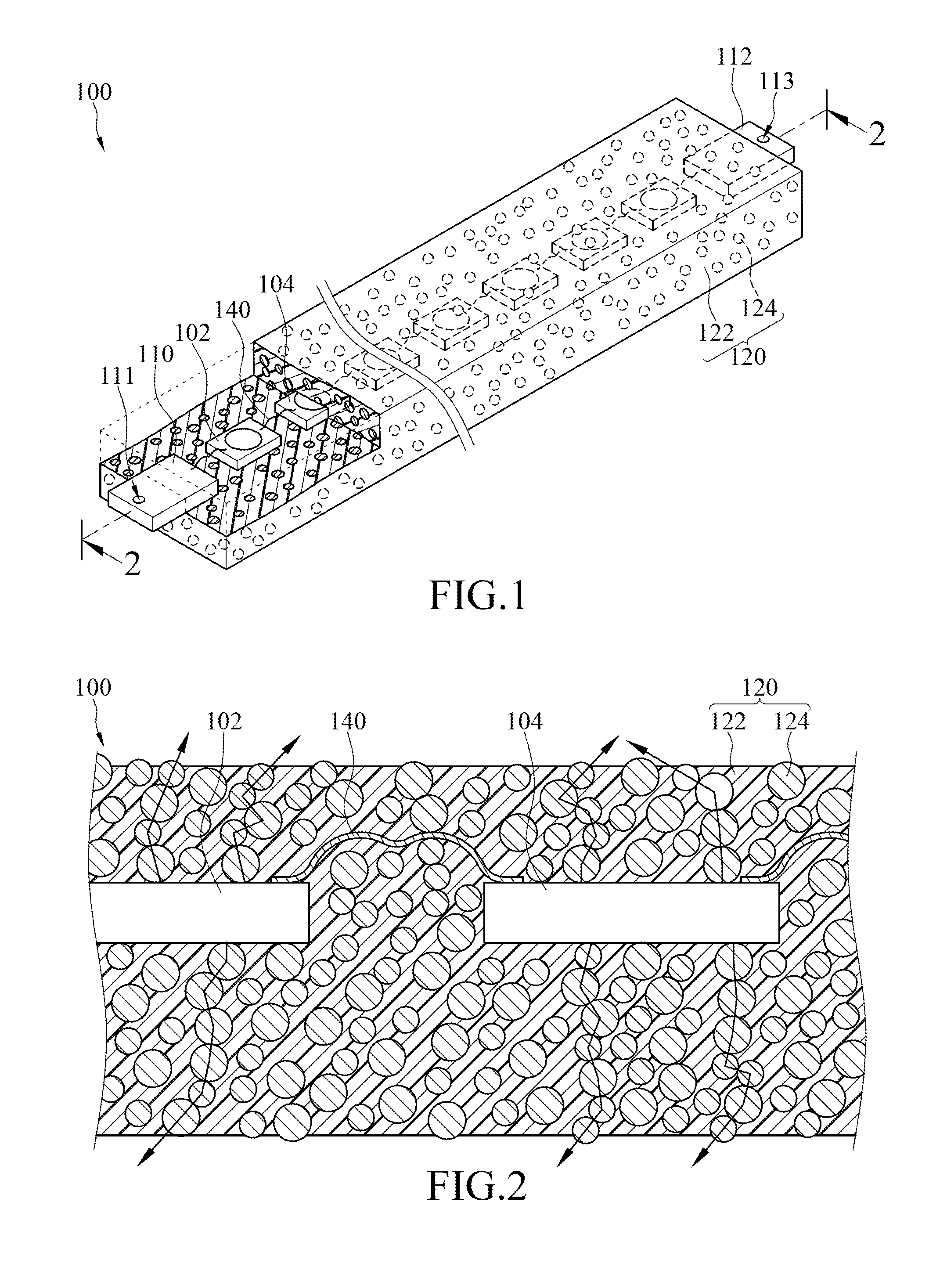
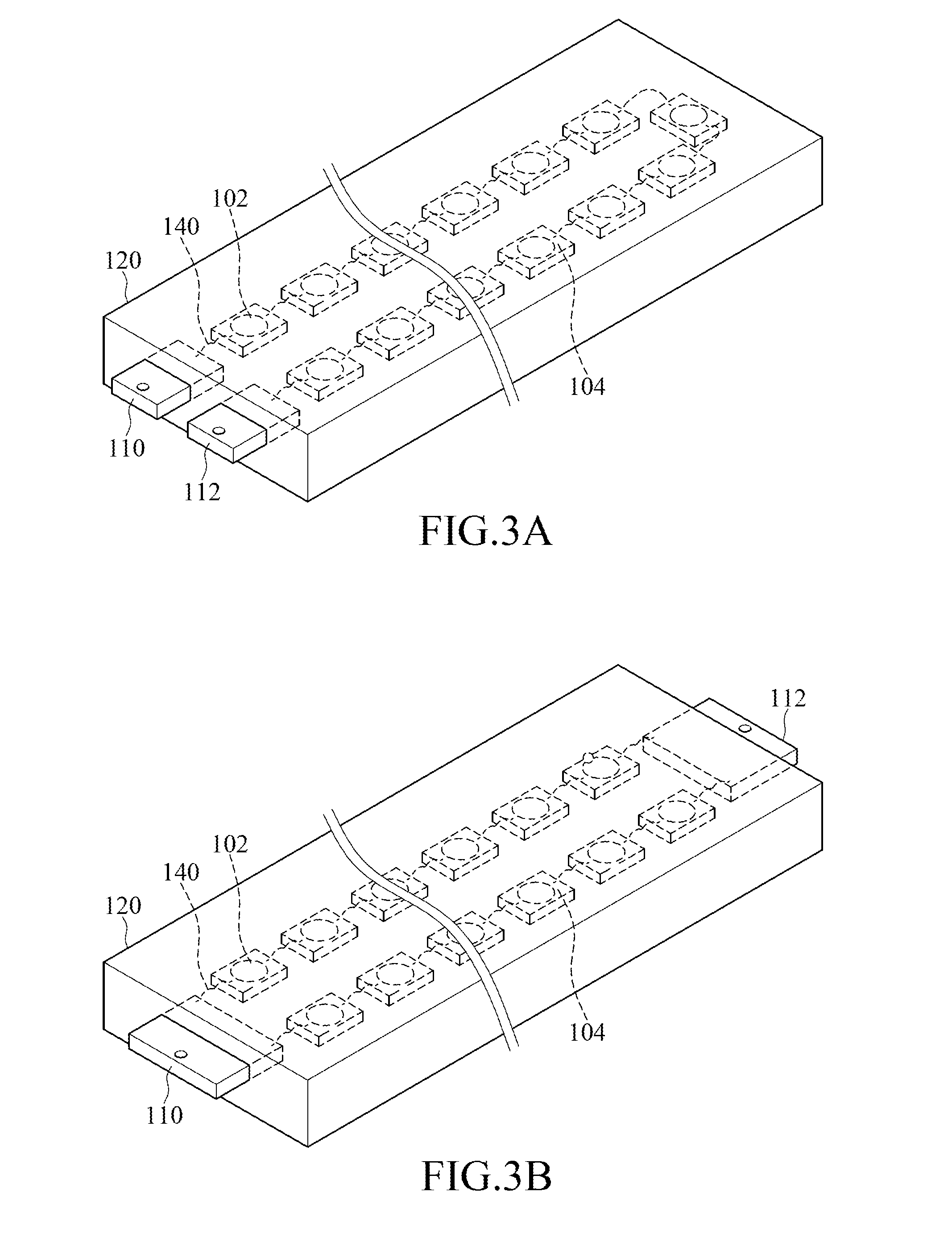
[0103]S204: dispose a plurality of LED chips 102, 104 and a plurality of conductive electrodes 110,112 on the conductive foil 130, referring to FIG. 11B;

[0104]S22: electrically connect the LED chips 102, 104 with the conductive electrodes 110, 112, referring to FIG. 11C; and

[0105]S24: coat a light conversion sub-layer (top layer 120a) on the surfaces of the LED chips 102, 104 and the conductive electrode 110, 112 where are not in contact with the base layer 120b. The light conversion coating 120 (including the base layer 120b and the top layer 120a) coats on at least two sides of the LED chips 102, 104 and the conductive electrodes 110, 112. The light conversion coating 120 exposes a portion of a...


PUM

PropertyMeasurementUnit
Fractionaaaaaaaaaa
Fractionaaaaaaaaaa
Fractionaaaaaaaaaa

Abstract

An LED filament and an LED light bulb applying the same are disclosed. The LED filament includes LED chips, conductive electrodes disposed corresponding to the LED chips, and a light conversion coating. The LED chips are electrically connected together and the conductive electrodes are electrically connected with the LED chips. The light conversion coating includes an adhesive and a plurality of phosphors. The light conversion coating coats on at least two sides of the LED chips and the conductive electrodes. The light conversion coating exposes a portion of two of the conductive electrodes. Accordingly, the LED filament is capable of emitting light similar to that a point light source does and the LED light bulb may emit omnidirectional light.

Description

CROSS-REFERENCE TO RELATED APPLICATIONS[0001]This application claims priority to the following Chinese Patent Applications No. CN 201510502630.3 filed on 2015 Aug. 17, CN 201510966906.3 filed on 2015 Dec. 19, CN 201610041667.5 filed on 2016 Jan. 22, CN 201610272153.0 filed on 2016 Apr. 27, CN 201610281600.9 filed on 2016 Apr. 29, CN 201610394610.3 field on 2016 Jun. 3, and CN 201610586388.7 filed on 2016 Jul. 22, the disclosures of which are incorporated herein in their entirety by reference.TECHNICAL FIELD[0002]The instant disclosure relates to illumination field, and more particularly, to an LED light bulb and an LED filament thereof.RELATED ART[0003]The LED has advantages of environmental protection, energy saving, high efficiency and long lifespan, and therefore it attracts widespread attention in recent years and gradually replaces traditional lighting lamps. However, due that the luminescence of the LED has directivity, current LED lamps is unable to provide with an illuminati...

Claims


Application Information

Patent Timeline
IPC IPC(8): F21K9/232H01L33/62H01L33/50H01L33/56F21V3/02F21V29/85F21V7/22F21V19/00F21V23/00F21K9/238F21K9/237H01L25/075F21K9/235F21V9/40
CPCF21K9/232H01L25/0753H01L33/62H01L33/502H01L33/56F21V3/02F21V29/85F21V7/22F21V19/006F21V23/002F21K9/238F21K9/237F21K9/235F21V19/0025F21V9/30F21V9/40F21K9/90F21V19/003F21Y2115/10F21Y2103/33F21Y2103/37F21Y2107/00H01L33/501H01L2224/45014H01L2224/48137F21V3/062F21V3/061H01L33/505H01L33/54F21K9/64
Inventor JIANG, TAOLI, LI-QIN
Owner JIAXING SUPER LIGHTING ELECTRIC APPLIANCE
Why Eureka
Try Eureka