
Image processing method, image processing apparatus, and recording medium

a technology of image processing and recording medium, applied in image analysis, image enhancement, instruments, etc., can solve the problems of insufficient coarse-to-fine search methods, insufficient detection of work, and difficulty in selecting edge to be used as a model and controlling parameters, etc., to achieve high accuracy, high robustness, and high speed

Active Publication Date: 2017-02-23
CANON KK
View PDF0 Cites 9 Cited by
  • Summary
  • Abstract
  • Description
  • Claims
  • Application Information

AI Technical Summary

Benefits of technology

The present invention is a method for high-speed, high-accuracy pattern matching. It involves calculating a model pyramid with different layers and size reduction factors, and a search target pyramid with the same layers and edges. The model pyramid is generated based on maximum size reduction factors calculated for edges, which prevents unstable edges from being generated. This results in a more stable and accurate model for pattern matching.

Problems solved by technology

In general, in a case where the coarse-to-fine search method is employed, an edge of a low resolution is also taken into consideration, and therefore, it is difficult to select an edge to be used as a model and to control parameters.
If the size reduction is performed without taking a degree of a feature into consideration, there arises a problem in that an edge having a feature of a small degree blurs and becomes unstable due to environmental influence, and as a result, a detection of a work fails.
Furthermore, if the size reduction which causes a blur of an edge is not performed taking a size of an edge into consideration, the coarse-to-fine search method may not be sufficiently performed at high speed.
If a large size reduction factor may not be set, processing employing the coarse-to-fine search method may not be sufficiently performed at high speed.
On the other hand, even in a case where a large size reduction factor may be set since a degree of sharpness is high, if an edge is small, it is likely that the image includes am unstable edge, such as a blur of an edge described above, and accordingly, detection is unstable.

Method used


Image

  • Image processing method, image processing apparatus, and recording medium
  • Image processing method, image processing apparatus, and recording medium
  • Image processing method, image processing apparatus, and recording medium

Examples


first embodiment

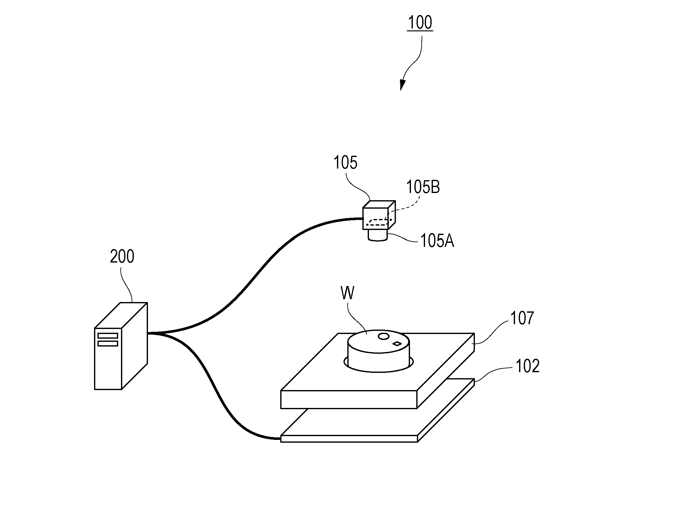
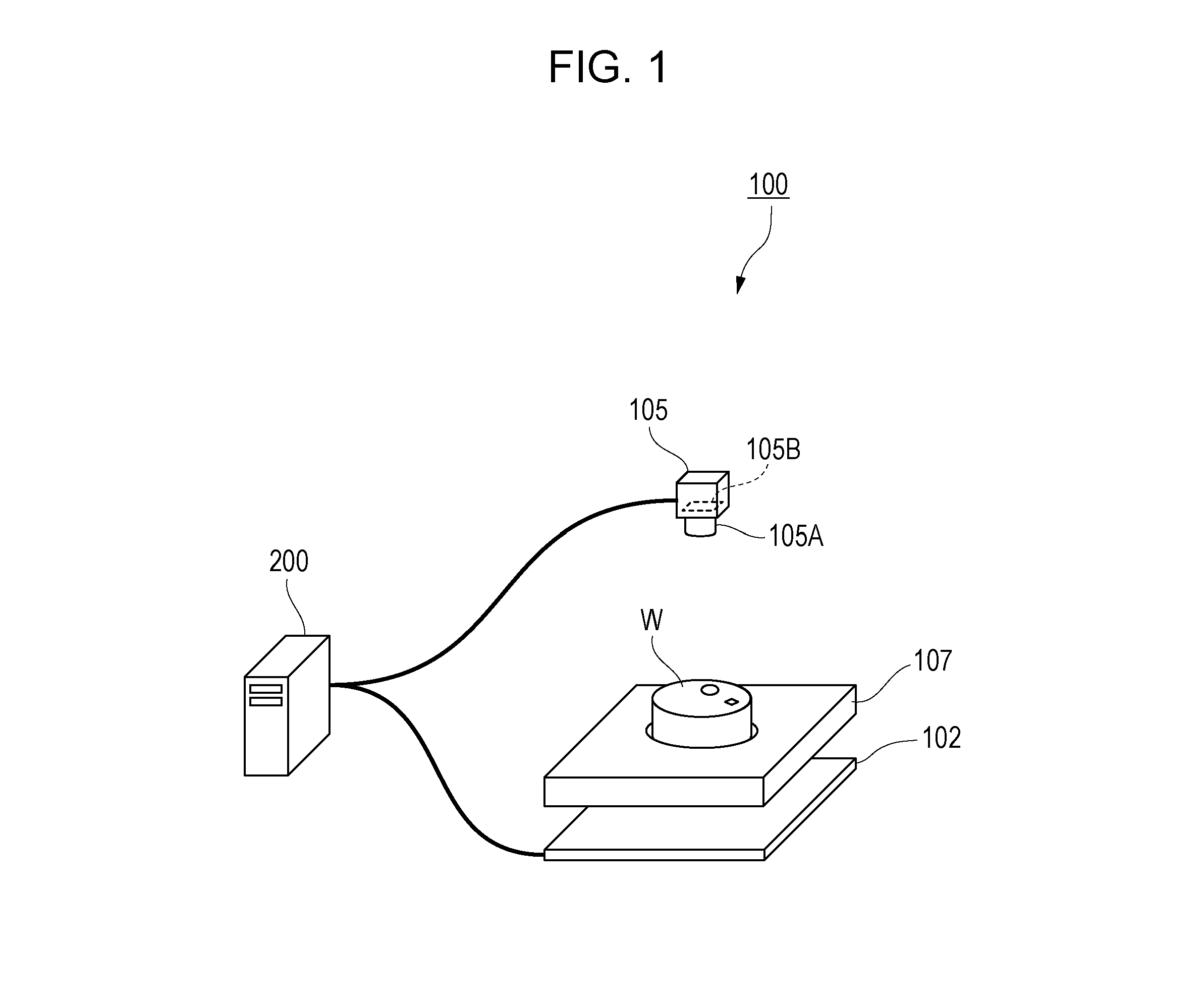
[0028]FIG. 1 is a diagram illustrating an image processing system including an image processing apparatus according to a first embodiment of the present invention. An image processing system 100 includes a light source 102, a camera 105 serving as an imaging apparatus, and an image processing apparatus 200. The light source 102 and the camera 105 are connected to the image processing apparatus 200. A work W which is a detection target object (an object) is held on a work holding stage 107.

[0029]The light source 102 is an illumination apparatus which emits (illuminates) light to the work W. Any light source, such as an LED or a halogen lamp, may be employed as the light source 102 as long as the light source 102 emits light of a light amount required for image processing to the work W.

[0030]The camera 105 is a digital still camera which generates data on a captured image by receiving light from the work W. The camera 105 includes an imaging lens 105A and an imaging device (a solid-st...

second embodiment

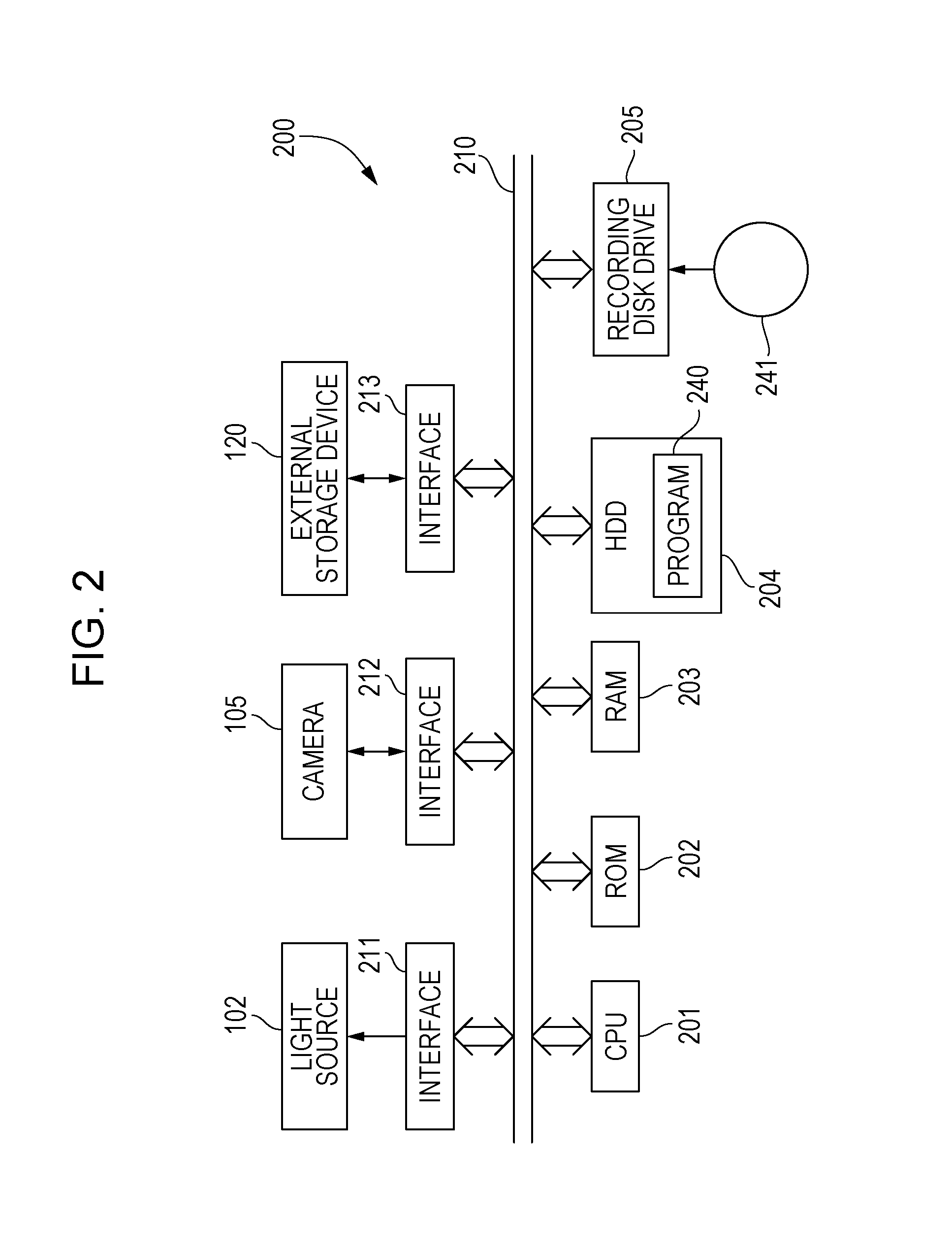
[0087]Next, an image processing method according to a second embodiment of the present invention will be described. FIG. 12 is a flowchart illustrating the image processing method according to the second embodiment of the present invention. A configuration of an image processing apparatus according to the second embodiment is the same as that of the first embodiment, but the second embodiment is different from the first embodiment in a process of a CPU 201, that is, a program 240, and more specifically, a method for generating a model pyramid. In the second embodiment, as with the first embodiment, the CPU 201 executes steps (processes) of the image processing method (a model pyramid generation method) illustrated in FIG. 12 in accordance with the program 240.

[0088]The CPU 201 obtains a model pyramid based on a reference image (S21 to S27: a model pyramid calculation step or a model pyramid calculation process). Here, the process from step S21 to step S25 illustrated in FIG. 12 is t...


PUM


Abstract

A processor performs pattern matching on a search target image using a reference image. The processor uses the reference image to calculate a model pyramid, which has model edges and different layers, and uses the search target image to calculate the search target pyramid, which has search target edges and layers having size reduction factors which are the same as those of the model pyramid. The processor performs pattern matching on the search target pyramid using the model pyramid. Calculation of the model pyramid includes (i) extracting and calculating sizes of edges from the reference image, (ii) obtaining maximum size reduction factors of the individual edges, and (iii) setting an edge (a) which has a size reduction factor equal to or larger than a target layer size reduction factor and (b) which has been subjected to size reduction as a model edge of the target layer.

Description

BACKGROUND OF THE INVENTION[0001]Field of the Invention[0002]The present invention relates to an image processing method for performing pattern matching based on a shape using a coarse-to-fine search method, an image processing apparatus, and a recording medium.[0003]Description of the Related Art[0004]In general, in a field of image processing, pattern matching has been widely used as a method for detecting an object (a work) and measuring a position of the object. In particular, pattern matching based on a shape has been widely used since a degree of similarity is calculated only using a portion including a feature of a shape in an image, and therefore, the shape pattern matching is performed at high speed.[0005]In the shape pattern matching, a degree of similarity is calculated using features of shapes of a reference image obtained by capturing a work in an ideal state and a search target image obtained by capturing a target work, and therefore, extraction of the features of shap...

Claims


Application Information

Patent Timeline
Patent Type & Authority Applications(United States)
IPC IPC(8): G06T7/00
CPCG06T2207/10004G06T7/0085G06T7/74G06T2207/20016
Inventor ODAGIRI, JUN
Owner CANON KK
Learn More