Welding apparatus

a welding apparatus and welding head technology, applied in the field of welding apparatus, can solve the problems of complicated power supply wire winding operation of the welding apparatus, large manufacturing cost, complicated control device structure, etc., and achieve the effects of reducing the radial dimension of the welding head turning gear, reducing processing cost, and lightening weigh

Active Publication Date: 2017-03-02
CUTLAND JAPAN
View PDF0 Cites 11 Cited by
  • Summary
  • Abstract
  • Description
  • Claims
  • Application Information

AI Technical Summary

Benefits of technology

[0011]Since the housing in annular shape has the guide surface continuous in the circumferential direction of the facing surfaces in the axial direction, and the welding head turning gear and the ring gear are rotatably supported with respect to the housing by the guide member with respect to the guide surface, a large-sized roller need not be provided for supporting the welding head turning gear as in a conventional art. Thus, as a radial dimension of the welding head turning gear can be reduced, the welding apparatus can be lighter in weight and more compact in size compared to the conventional art.
[0012]Furthermore, if the ring gear is provided pivotably only at a predetermined angle with respect to the welding head turning gear, and the external or internal teeth engaged with the ring out...

Problems solved by technology

The above-described winding operation of the power supply wire in the welding apparatus is complicated, which has been an obstacle to efficient welding work.
However, in the welding apparatus disclosed in Patent Document 1, the rotating speed of each of the electric motors should be controlled separately, which complicates the structure of a control device as well as a large manufacturing cost thereof.
In addition, the welding apparatus may easily increase in size and weight from the following viewpoints.
First, the housing itself moves forward and backward in the axial direction of the pipe using the ball screw mechanism, leading ...

Method used


Image

  • Welding apparatus
  • Welding apparatus
  • Welding apparatus

Examples


Embodiment Construction

[0024]Following is a description by way of example only with reference to FIGS. 1 to 9 of embodiments of the present disclosure. Still, the present disclosure is not limited to these embodiments.

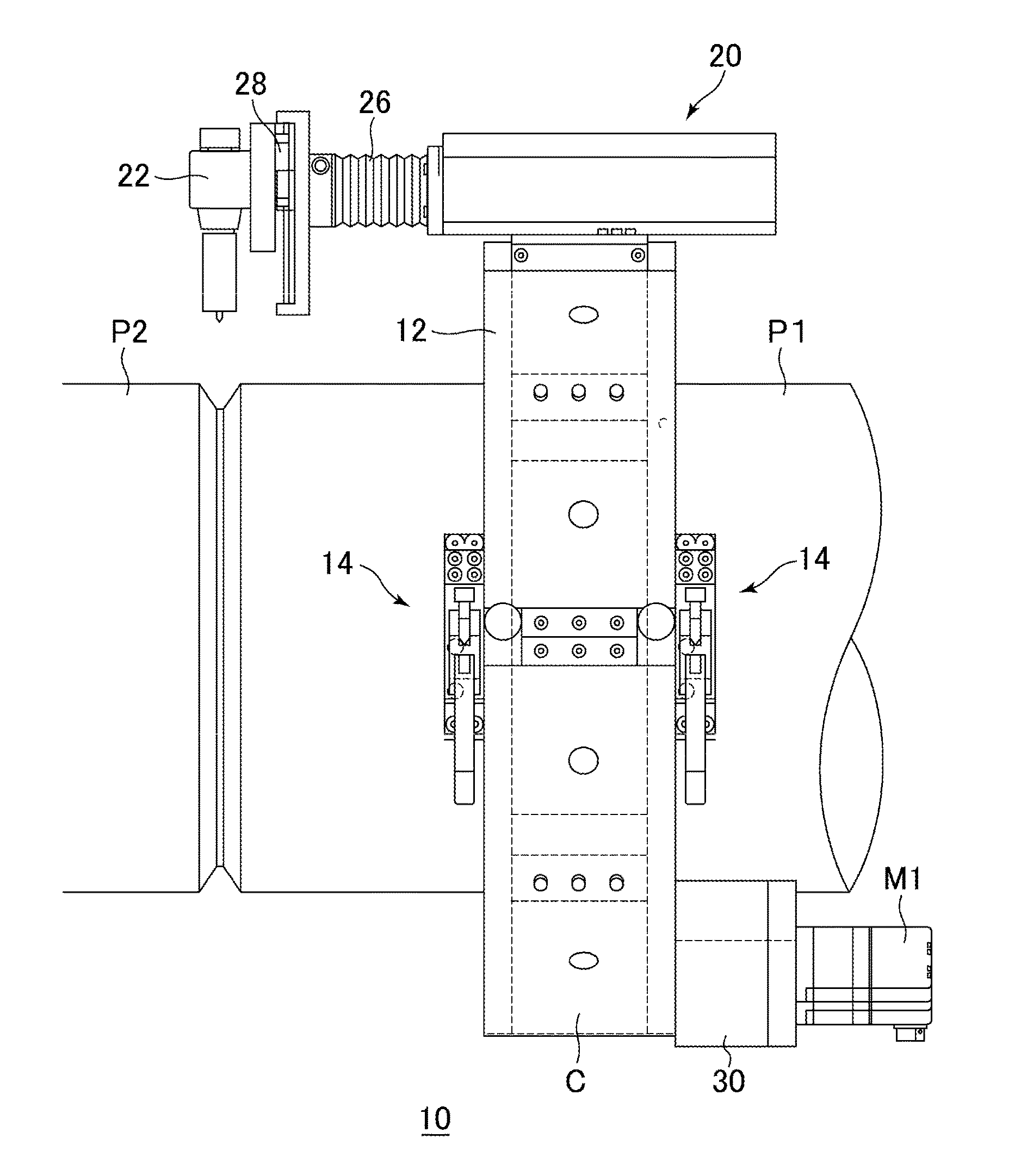
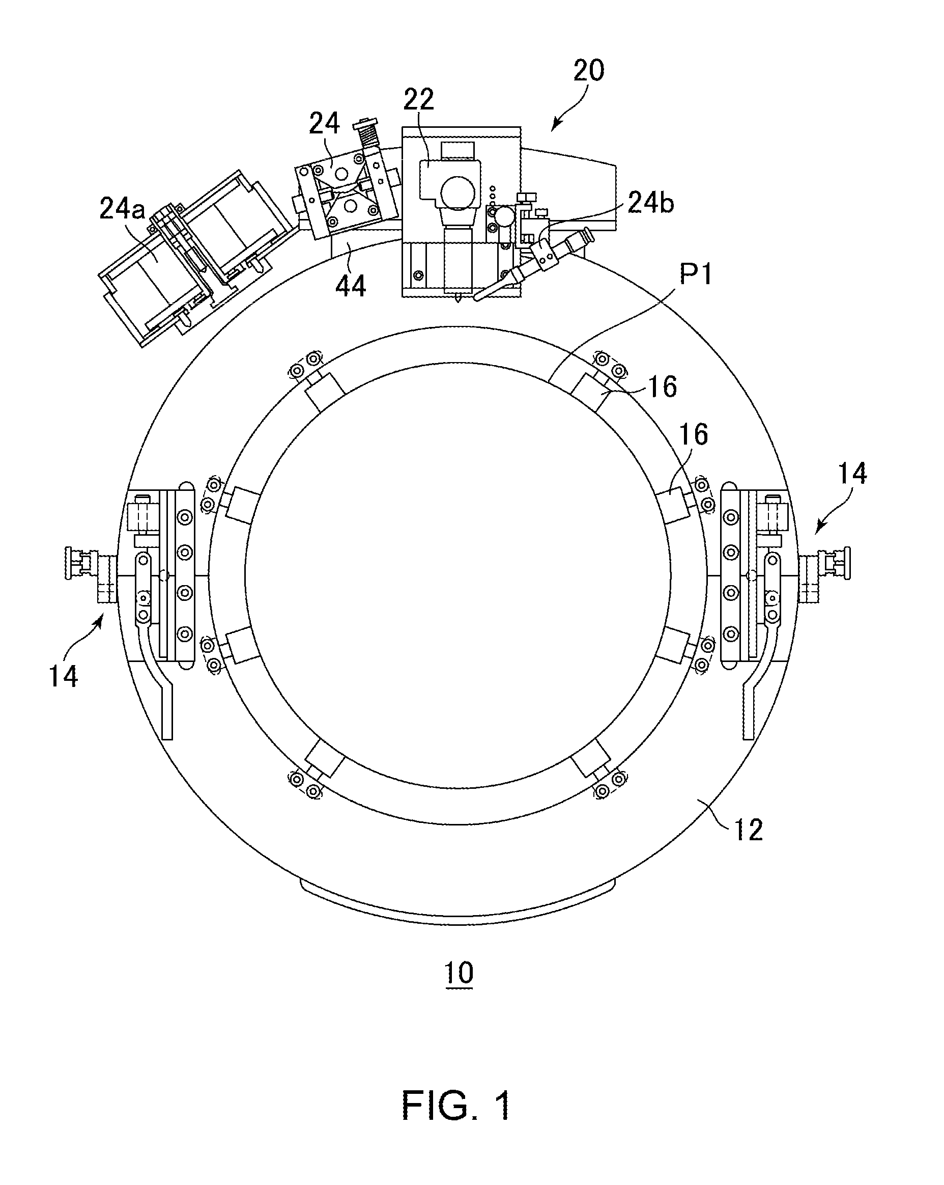
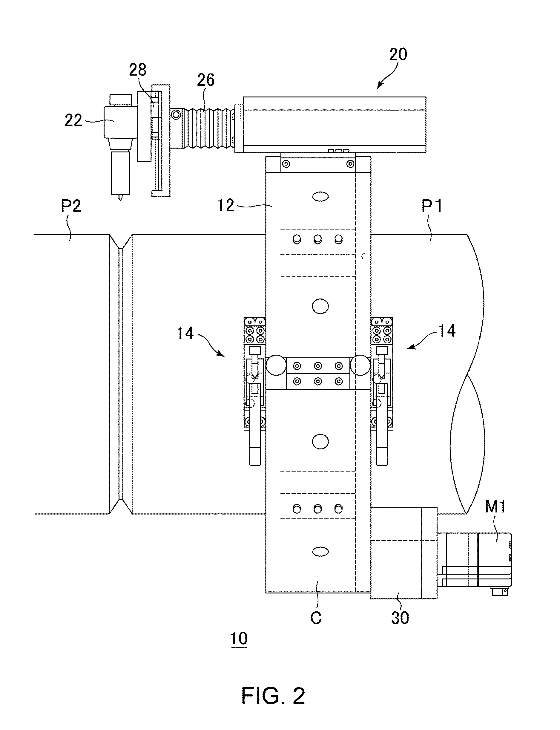
[0025]FIGS. 1 to 3 are views respectively illustrating the front, side and rear views of a welding apparatus 10 of the first embodiment. As shown in these figures, the welding apparatus 10 includes a housing 12 in annular shape. The housing 12 is fixed by a plurality of fixing members 16, provided in the circumferential direction, on an outer peripheral surface of the pipe P1, which is an example of a workpiece. Also, the housing 12 is configured to have facing surfaces 13, 13 in the axial direction (see FIG. 6) and be separable into top and bottom sections, which are shown in the figures to be coupled by a coupling tool 14. Remarkably, the housing is separable into more than two sections.

[0026]As shown in FIG. 2, when the pipe P1 and a pipe P2 are welded together, the welding apparatus 10 i...


PUM

PropertyMeasurementUnit
Weightaaaaaaaaaa
Angleaaaaaaaaaa
Speedaaaaaaaaaa

Abstract

A welding apparatus includes a housing having facing surfaces in the axial direction, and a welding head turning gear and first to third ring gears inside of the housing. A guide surface is formed on the facing surfaces. The welding head turning gear is coupled to a guide member, and the first to third ring gears are supported by the welding head turning gear and the guide member. Since a roller provided to the guide member rolls on the guide surface to rotatably support the first to third ring gears with respect to the housing, the welding apparatus can be lighter in weight and more compact compared to a conventional welding apparatus.

Description

FIELD OF THE INVENTION[0001]The present disclosure relates to an apparatus for welding a workpiece to be welded that is cylindrical in shape, or specifically, a pipe. Hereinafter, such device will be referred to simply as “welding apparatus.”DESCRIPTION OF RELATED ART[0002]A welding apparatus for welding a pipe by pivoting a welding torch in the circumferential direction of the pipe is known conventionally. Generally, in such welding apparatus, since a power supply wire connected to the welding torch winds around an outer peripheral surface of the pipe when the welding torch pivots in the circumferential direction of the pipe, the power supply wire needs to be wound beforehand around the outer peripheral surface of the pipe in a direction opposite to the pivoting direction of the welding torch.[0003]The above-described winding operation of the power supply wire in the welding apparatus is complicated, which has been an obstacle to efficient welding work. Under such circumstances, a ...

Claims


Application Information

Patent Timeline
IPC IPC(8): B23K9/028B23K37/02
CPCB23K9/0286B23K2201/06B23K37/0217B23K37/0211B23K37/0276B23K37/0282B23K2101/06
Inventor MORI, KENICHI
Owner CUTLAND JAPAN
Why Eureka
Try Eureka