Single Phase Permanent Magnet Motor And Method For Making Same

a permanent magnet motor and single-phase technology, applied in the direction of synchronous motors, magnetic circuit rotating parts, magnetic circuit shapes/forms/construction, etc., can solve the problems of small startup angle, motor generating vibration and noise, motor generating small startup angle, etc., to achieve rapid finishing of the winding of the stator and easy bendability

Inactive Publication Date: 2017-03-02
JOHNSON ELECTRIC SA
View PDF5 Cites 5 Cited by
  • Summary
  • Abstract
  • Description
  • Claims
  • Application Information

AI Technical Summary

Benefits of technology

[0004]Thus, there is a desire for a new single phase permanent magnet motor which can facilitate winding and increase the startup reliability.
[0019]In another aspect, a method for making a single phase permanent magnet motor is provided, which includes the steps of: configuring a stator core, wherein the stator core comprises a first ring portion, a plurality of tooth bodies extending radially from the outer ring portion, and a pole shoe extending from a radial distal end to two circumferential sides of each tooth body, a slot opening is defined between each two adjacent pole shoes, at least one of the two adjacent pole shoes includes a main portion, a connecting portion and an easily bendable tip sequentially arranged in a circumferential direction of the stator, the easily bendable tip is bent relative to the main portion about the connecting portion; winding a stator winding around the stator core; and bending the easily bendable tip about the connecting portion to narrow the slot opening.
[0022]Preferably, the pole shoe has a reduced radial size at the connecting portion thereof for facilitating bending the easily bendable tip about the connecting portion.
[0024]In the single phase permanent magnet motor of the present invention, at least one of two adjacent pole shoes is provided with an easily bendable tip, and the easily bendable tip is bendable for changing the distance between the two adjacent pole shoes, thus more rapidly finishing the winding of the stator winding.

Problems solved by technology

The presence of the slot openings can make the motor generate an unduly large cogging torque.
The cogging torque can result in the motor generating vibration and noise.
Furthermore, because of the limitation of the slot openings, the motor has a small startup angle and poor startup reliability.

Method used


Image

  • Single Phase Permanent Magnet Motor And Method For Making Same
  • Single Phase Permanent Magnet Motor And Method For Making Same
  • Single Phase Permanent Magnet Motor And Method For Making Same

Examples


first embodiment

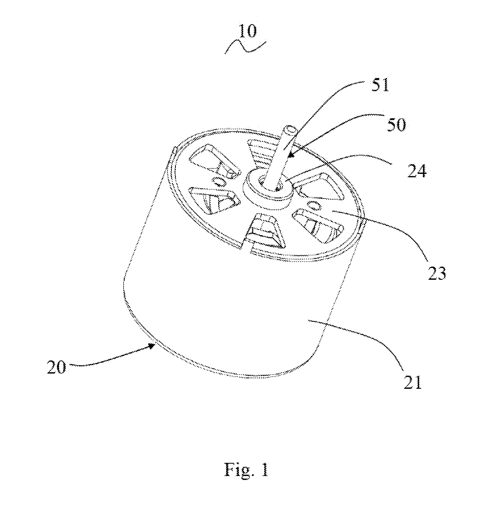
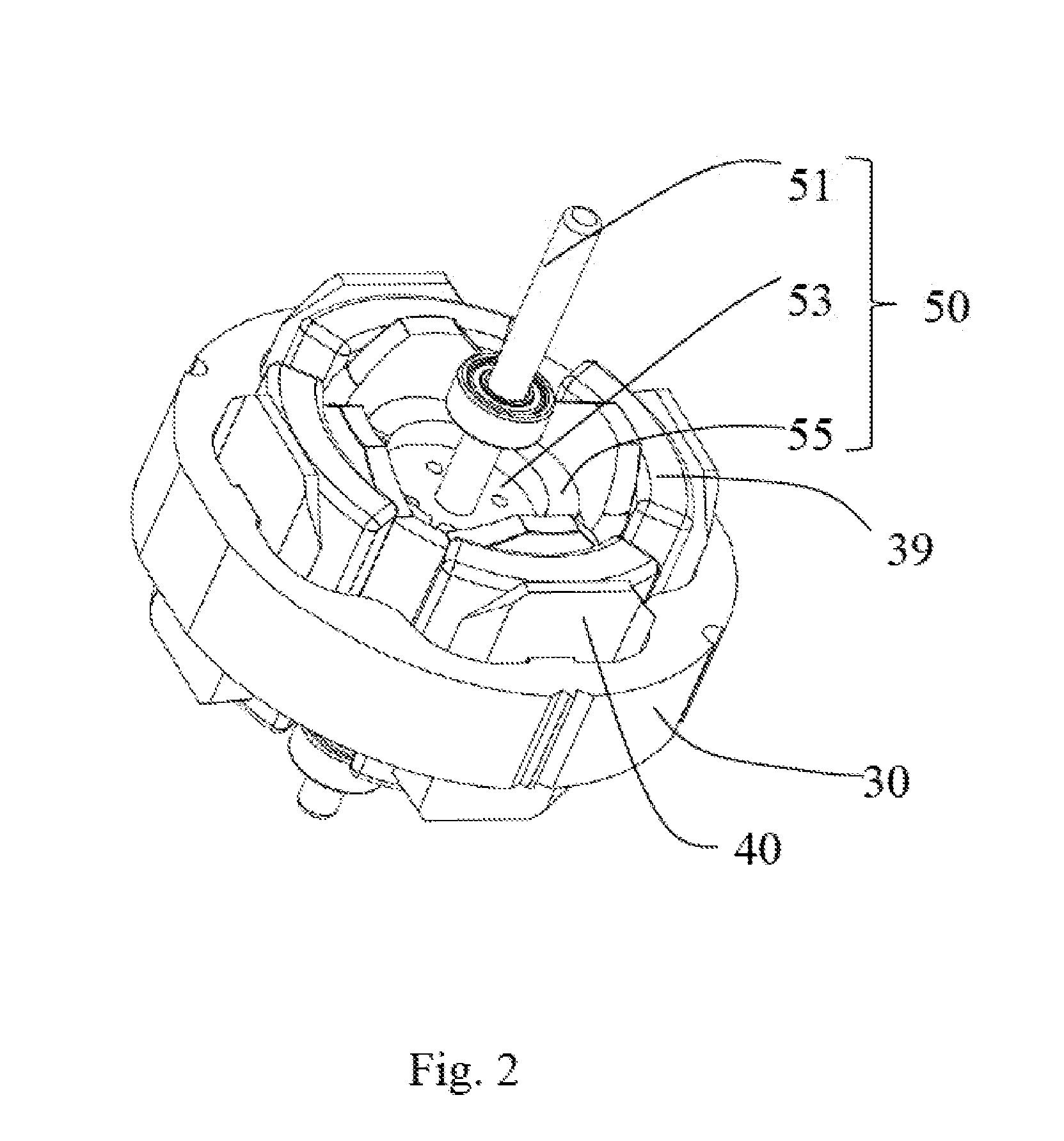
[0036]Referring to FIG. 1 to FIG. 6, the single phase permanent magnet motor 10 in accordance with a preferred embodiment of the present invention includes a stator 20 and a rotor 50 rotatable relative to the stator.

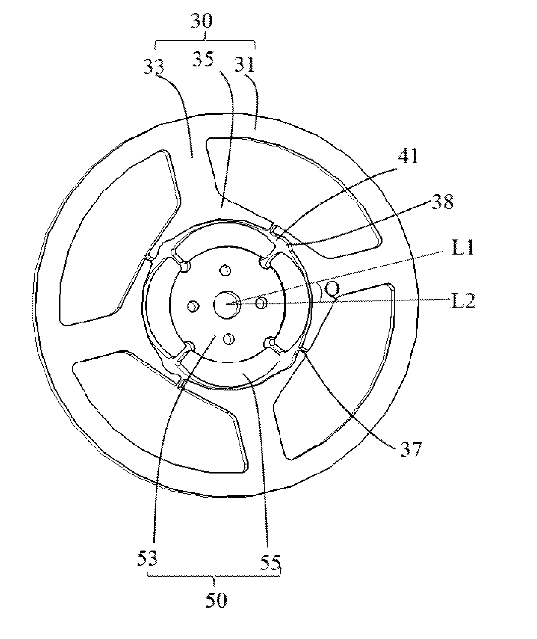
[0037]The stator 20 includes a cylindrical outer housing 21 with one open end, an end cap 23 mounted to the open end of the outer housing 21, a stator core 30 mounted in the outer housing 21, an insulating winding bracket 40 mounted to the stator core 30, and a stator winding 39 wound around the stator core 30 and supported by the insulating winding bracket 40. The stator core 30 includes an outer ring portion 31, a plurality of tooth bodies 33 extending inwardly from the outer ring portion 31, and a pole shoe 35 extending from a radial inner end to two circumferential sides of each tooth body 33. The stator winding 39 is wound around the tooth bodies 33. A slot opening 37 is defined between each two adjacent pole shoes 35. The slot opening 37 may be disposed at a middle...

second embodiment

[0049]Referring to FIG. 7, a main difference between this embodiment and the first embodiment is that, the positioning slot 38 is disposed between an outer circumferential surface and the inner circumferential surface of the pole shoe 35 in the form of a through hole or blind hole. Preferably, the positioning slot 38 is disposed in the connecting portion of the pole shoe 35 (i.e. see FIG. 5, between the main portion 35a and the easily bendable tip 35c of the pole shoe 35). Because of the presence of the positioning slot 38, the part of the pole shoe 35 corresponding to the positioning slot 38 has a reduced thickness and can be easy to bend.

[0050]In addition, the rotor 60 includes a plurality of permanent magnetic poles 65 arranged along the circumferential direction of the rotor 60. An outer surface of each permanent magnetic pole 65 is an arc surface. Each permanent magnetic pole 65 is formed by a permanent magnet, and the permanent magnet is mounted to an outer circumferential sur...

third embodiment

[0051]The rotor 70 of this embodiment is different from the rotors 50 and 60 of the above two embodiments. Referring to FIG. 8, the permanent magnetic poles 75 of this embodiment are formed by a plurality of permanent magnets 76, such as four permanent magnets 76. The outer circumferential surface of the rotor core 73 defines a plurality of axially-extending grooves 74. Each groove 74 is disposed at a junction of two adjacent permanent magnets 76 to reduce magnetic leakage. The permanent magnets 76 are mounted to the outer circumferential surface of the rotor core 73. In this case, the inner surfaces of the pole shoes 35 are located on a circle centered at the center of the rotor 70 in an axial plane view. The outer surfaces of all the permanent magnets 76 cooperatively form a cylindrical surface centered at the center of the rotor 70 so as to make the air gap form an even air gap.


PUM


Abstract

A single phase permanent magnet motor and a method for making the same are provided. The method includes the steps of: configuring a stator core, wherein the stator core comprises a first ring portion, tooth bodies, and a pole shoe extending from each tooth body, a slot opening is defined between each two adjacent pole shoes, at least one pole shoe includes a main portion, a connecting portion and an easily bendable tip, the easily bendable tip is bent relative to the main portion about the connecting portion; winding a stator winding around the stator core; and bending the easily bendable tip about the connecting portion to narrow the slot opening. The present invention can change the size of the slot opening, thus more rapidly finishing the winding of the stator winding and enhancing the efficiency of the motor fabrication.

Description

CROSS REFERENCE TO RELATED APPLICATIONS[0001]This non-provisional patent application claims priority under 35 U.S.C. §119(a) from Patent Application No. 201510543384.6 filed in The People's Republic of China on Aug. 28, 2015.FIELD OF THE INVENTION[0002]The present invention relates to single phase permanent magnet motors, and a method for making the single phase permanent magnet motor.BACKGROUND OF THE INVENTION[0003]In a conventional single phase permanent magnet motor, a stator core is provided as an integral structure, i.e. an outer ring portion and teeth are formed at the same time into an integral structure. Large slot openings are formed between pole shoes of adjacent teeth. The presence of the slot openings can make the motor generate an unduly large cogging torque. The cogging torque can result in the motor generating vibration and noise. Furthermore, because of the limitation of the slot openings, the motor has a small startup angle and poor startup reliability.SUMMARY OF T...

Claims


Application Information

Patent Timeline
Patent Type & Authority Applications(United States)
IPC IPC(8): H02K19/04H02K1/16H02K15/095H02K3/18H02K15/02H02K1/14H02K1/27
CPCH02K19/04H02K1/146H02K1/16H02K15/095H02K3/18H02K15/02H02K1/2706H02K29/03H02K1/278H02K2201/03H02K1/165H02K1/27H02K15/03H02K3/48H02K15/062
Inventor LI, YUEZHOU, CHUI YOUWANG, YONGLI, YONG
Owner JOHNSON ELECTRIC SA
Why Eureka
Try Eureka