
Method For Tuning A Motor Drive Using Frequency Response

a frequency response and motor drive technology, applied in adaptive control, process and machine control, instruments, etc., can solve the problems of less than optimum performance, unstable control system, time and labor-intensive iterative approach, etc., to achieve the desired level of performance, reduce computational intensity, and rapidly determine the frequency response

Active Publication Date: 2017-03-02
ROCKWELL AUTOMATION TECH
View PDF4 Cites 7 Cited by
  • Summary
  • Abstract
  • Description
  • Claims
  • Application Information

AI Technical Summary

Benefits of technology

The subject of this patent is an improved method for tuning a motor controller to achieve a desired level of performance. It involves measuring the frequency response of the system and setting controller gains and filter settings based on that response. The method reduces computational intensity and allows for faster tuning. Additionally, an adaptive tuning routine is used to adjust the controller gains and filter frequencies to maintain the desired level of performance while the motor continues to operate. This method ensures stable control and optimal performance.

Problems solved by technology

However, selecting the control gains to achieve a desired level of performance has certain challenges.
The interaction of control gains along various paths often requires a time and labor-intensive iterative approach to selecting control gains in order to achieve the desired level of performance.
Further, the final control gains selected often result in less than optimum performance in order to avoid approaching operating regions in which one of the control gains may result in instability of the control system.
However, existing automatic tuning procedures have certain drawbacks as well.
This poor tuning results in a system being controlled at less than its desired performance level, reducing the overall performance of the system.
The dynamics of the system may vary due, for example, to wear of mechanical equipment or repair and / or replacement with equipment having different characteristics than the original equipment.

Method used


Image

  • Method For Tuning A Motor Drive Using Frequency Response
  • Method For Tuning A Motor Drive Using Frequency Response
  • Method For Tuning A Motor Drive Using Frequency Response

Examples


Embodiment Construction

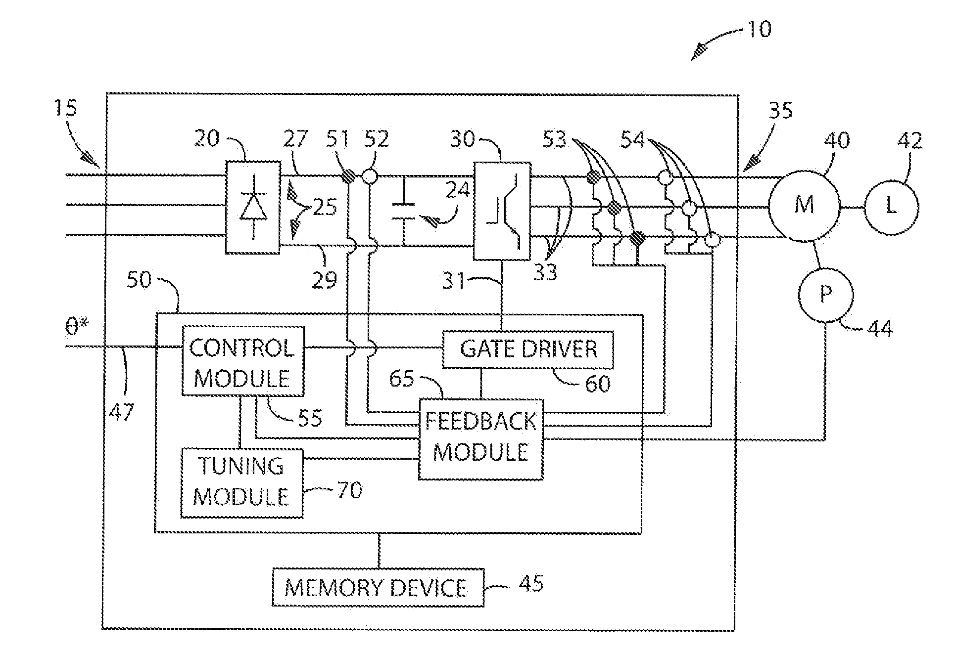
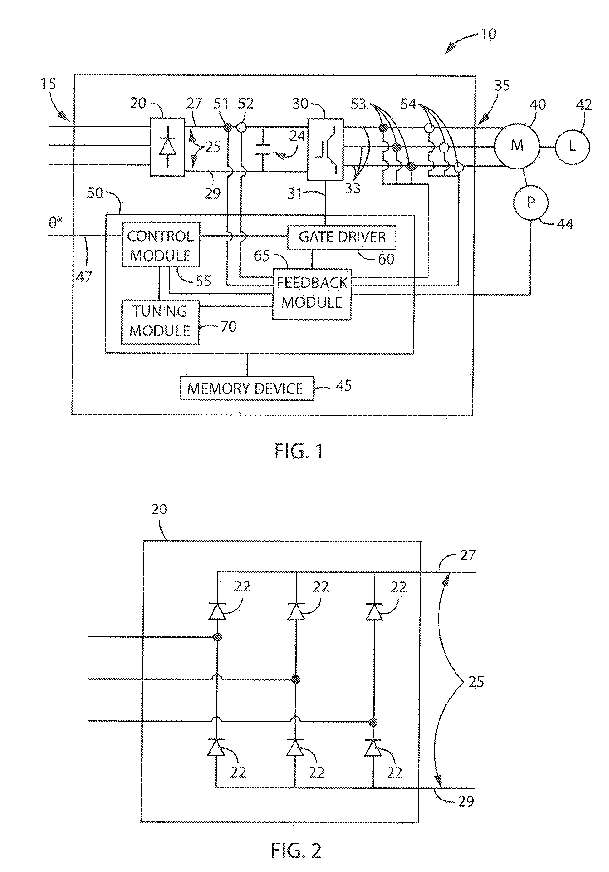
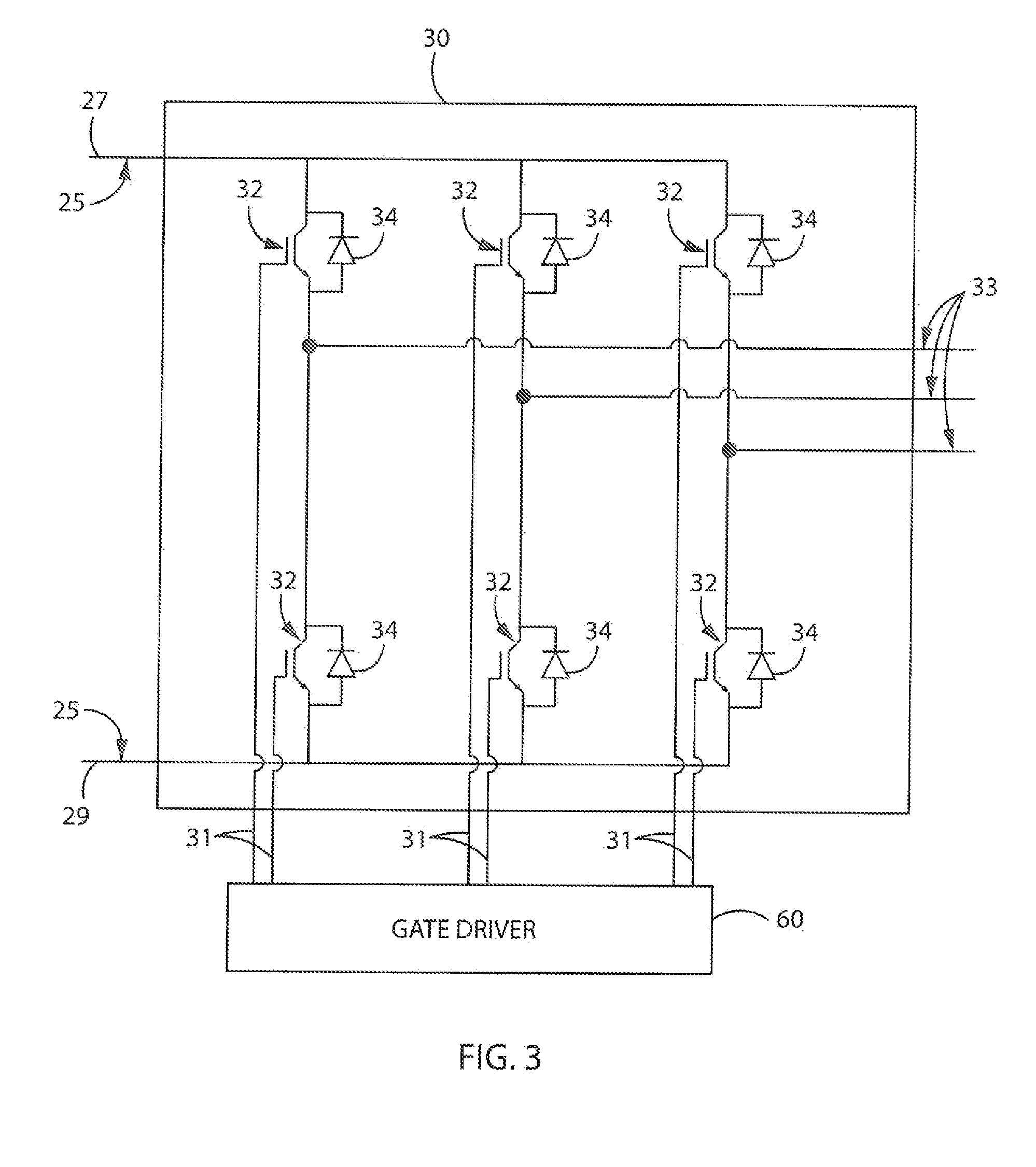
[0031]Turning initially to FIG. 1, a motor drive 10, according to one embodiment of the invention, is configured to receive a three-phase AC voltage at an input 15 of the motor drive 10 which is, in turn, provided to a rectifier section 20 of the motor drive 10. The rectifier section 20 may include any electronic device suitable for passive or active rectification as is understood in the art. With reference also to FIG. 2, the illustrated rectifier section 20 includes a set of diodes 22 forming a diode bridge that rectifies the three-phase AC voltage to a DC voltage on the DC bus 25. Optionally, the rectifier section 20 may include other solid state devices including, but not limited to, thyristors, silicon controlled rectifiers (SCRs), or transistors to convert the input power 15 to a DC voltage for the DC bus 25. The DC voltage is present between a positive rail 27 and a negative rail 29 of the DC bus 25. A DC bus capacitor 24 is connected between the positive and negative rails, ...


PUM


Abstract

An improved system for tuning a motor controller is disclosed. The controller gains are initially set based on the measured frequency response for the controlled system. A desired level of performance is defined by setting a desired phase margin and a desired gain margin to be observed in the frequency response. An improved method of determining the frequency response provides for a reduced computational intensity. The initial tuning routine uses the frequency response to set not only controller gains, but also settings for filters in the control module. Having obtained the desired level of performance from the initial tuning, the motor drive executes an adaptive tuning routine while controlling the motor. The adaptive tuning routine tracks changes in the operating performance and adjusts the filter settings or the controller gains to return operation to within the desired level of performance while the motor continues to operate.

Description

BACKGROUND OF THE INVENTION[0001]The subject matter disclosed herein relates generally to tuning a motor drive and, more specifically, to a method for tuning of a high performance motor drive system utilizing frequency response analysis.[0002]As is known to those skilled in the art, motor drives are utilized to control operation of a motor. According to one common configuration, a motor drive includes a DC bus having a DC voltage of suitable magnitude from which an AC voltage may be generated and provided to the motor. The DC voltage may be provided as an input to the motor drive or, alternately, the motor drive may include a rectifier section which converts an AC voltage input to the DC voltage present on the DC bus. The motor drive includes power electronic switching devices, such as insulated gate bipolar transistors (IGBTs), thyristors, or silicon controlled rectifiers (SCRs). The power electronic switching device further includes a reverse conduction power electronic device, su...

Claims


Application Information

Patent Timeline
Patent Type & Authority Applications(United States)
IPC IPC(8): H02P23/14G05B13/02
CPCG05B13/02H02P23/14H02P23/0004
Inventor DA SILVA, ADERIANO M.FAST, BRIANMIKLOSOVIC, ROBERT J.HOLT, MICHELLE E.
Owner ROCKWELL AUTOMATION TECH
Learn More